Manufacturing method for magnetic disk drive

a magnetic disk and manufacturing method technology, applied in special recording techniques, recording signal processing, instruments, etc., can solve the problems of nondefective sectors not causing reading errors, reading errors, and disk drives that suffer a further decrease in data reading capability, etc., to achieve high accuracy

Inactive Publication Date: 2010-02-16
WESTERN DIGITAL TECH INC
View PDF15 Cites 3 Cited by
  • Summary
  • Abstract
  • Description
  • Claims
  • Application Information

AI Technical Summary

Benefits of technology

[0011]Prior to product shipping, a defective sector not causing the defect to emerge until the magnetic disk drive has been placed into first use at such a low operating environmental temperature may be detected. In this case, read / write testing under a low-temperature operating environment is required. In addition, hence, vast equipment investments for improved testing environment such as low-temperature chamber. Also, read / write tests may be conducted under a normal-temperature or high-temperature operating environment with a further reduced number of ECC symbols or with a reduced soft-error rate (SER) threshold value for improved defect detection sensitivity. In this case, nondefective sectors not causing a reading error even in a low-temperature operating environment are also liable to be identified as defective sectors. If this actually happens, the resulting decrease in the capacity of the magnetic disk or increase in inspection time will also adversely affect the manufacturing yield of magnetic disk drives of the corresponding type.
[0020]The present invention makes it possible to provide the manufacturing method for a magnetic disk drive that includes the process of processing magnetic disk defective sectors with high accuracy. The present invention also makes it possible to provide the manufacturing method for a magnetic disk drive that includes a sector defect processing process suitable for ensuring the reliability of the magnetic disk drive. In addition, the present invention makes it possible to provide the manufacturing method for a magnetic disk drive that includes a simplified process in which the defective sectors causing a reading error when the magnetic disk drive is operated in a low-temperature operating environment are processed at normal temperature or high temperatures.

Problems solved by technology

The disk drive also tends to suffer a further decrease in data reading capability due to the frequency characteristics of a data-reading system.
This, in turn, indicates that although data reading at high operating environmental temperatures does not easily result in reading errors, there is a strong tendency for reading at low operating environmental temperatures to result in reading errors.
Prior to product shipping, a defective sector not causing the defect to emerge until the magnetic disk drive has been placed into first use at such a low operating environmental temperature may be detected.
In this case, nondefective sectors not causing a reading error even in a low-temperature operating environment are also liable to be identified as defective sectors.
If this actually happens, the resulting decrease in the capacity of the magnetic disk or increase in inspection time will also adversely affect the manufacturing yield of magnetic disk drives of the corresponding type.

Method used


Image

  • Manufacturing method for magnetic disk drive
  • Manufacturing method for magnetic disk drive
  • Manufacturing method for magnetic disk drive

Examples


Embodiment Construction

Configuration of a Magnetic Disk Drive

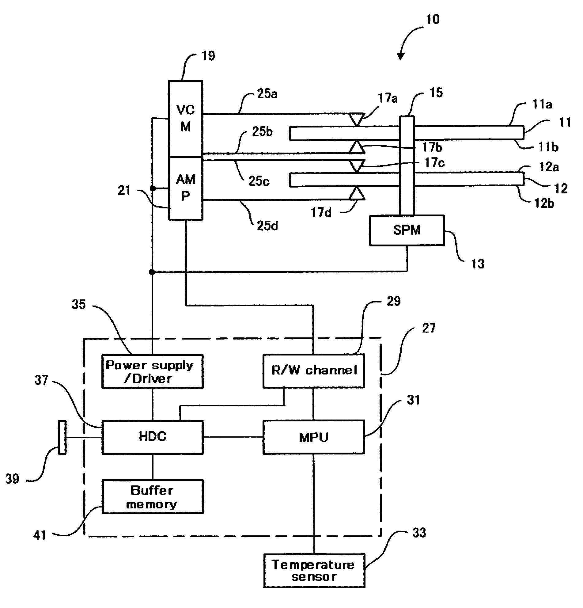
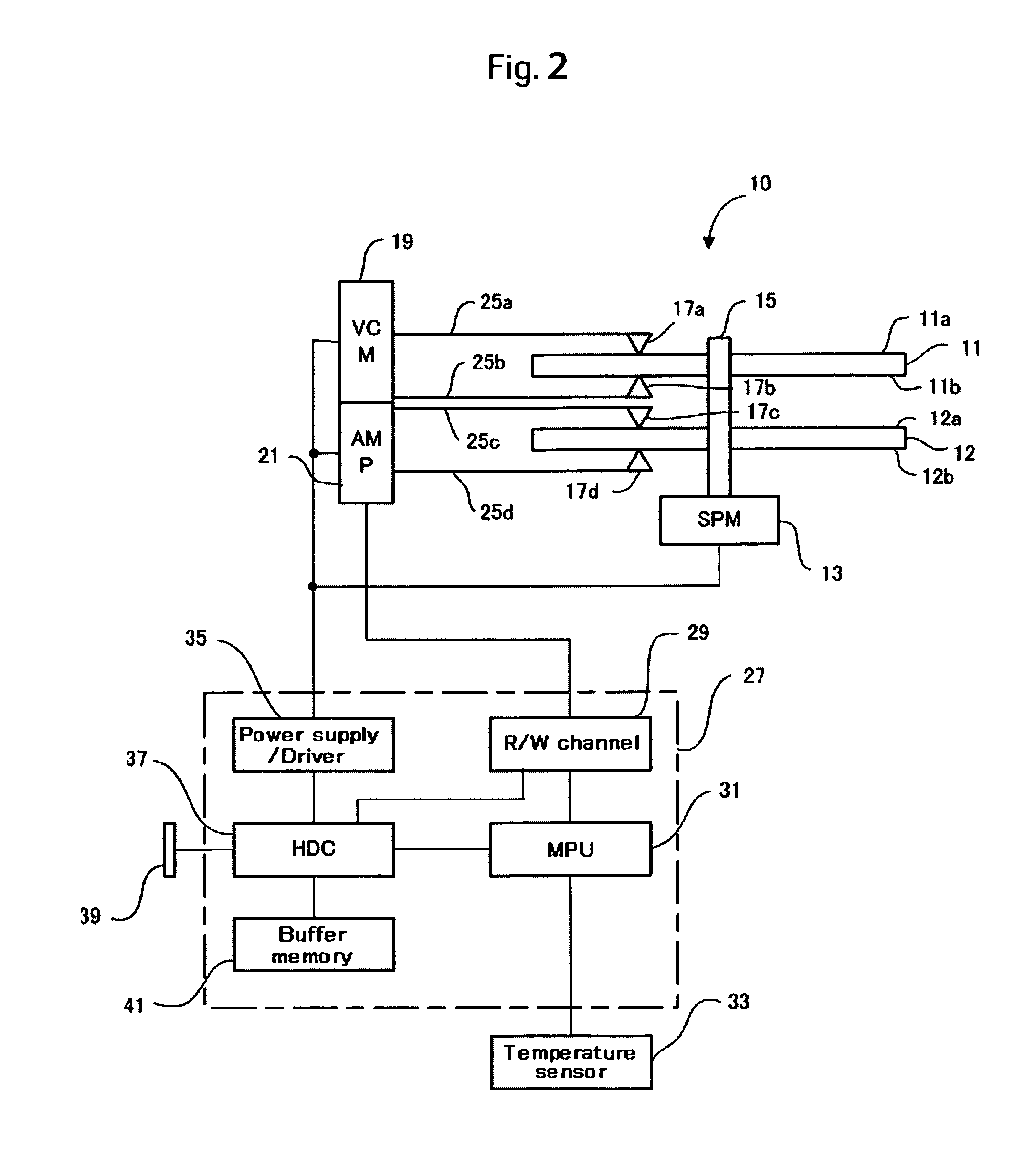
[0028]FIG. 2 is a schematic block diagram of a magnetic disk drive that processes defects in sectors by using a method according to an embodiment of the present invention. A magnetic disk drive 10 has two magnetic disks 11 and 12. The magnetic disk 11 has recording faces 11a and 11b, and the magnetic disk 12 has recording faces 12a and 12b. A magnetic layer for magnetic recording is formed on each recording face. Also, a protective layer is formed on top of the recording face. In addition, on each recording face, a plurality of data sectors are defined as a minimum unit of data recording, and servo data for magnetic head position control is recorded. Throughout this specification, the data sectors are hereunder referred to simply as sectors. The magnetic disks 11, 12 are fixed to a spindle 15 at desired spatial intervals, and both disks rotate together via a spindle motor (SPM) 13.

[0029]The magnetic disk drive 10 has four magnetic heads, 17a, 17...


PUM

PropertyMeasurementUnit
temperatureaaaaaaaaaa
temperaturesaaaaaaaaaa

Abstract

The present invention relates to providing the manufacturing method for a magnetic disk drive that includes the process steps of detecting and processing in a simplified way the defective sectors causing a reading error at low operating environmental temperatures. In one example, defective sectors are detected by read / write testing at high operating environmental temperatures from, for example, 40° C. to 65° C. Reading the data written on the defective sectors makes it obvious that the gain in a high-frequency band is reduced. After test data has been written onto each sector, the filtering coefficient of an FIR element that is set for a data-reading system is changed from the optimum value. The frequency gain is thus reduced. Next, the test data is read and the sectors that have caused a reading error are registered as defectives.

Description

CROSS-REFERENCES TO RELATED APPLICATIONS[0001]This application claims priority from Japanese Patent Application No. JP2004-362809, filed Dec. 15, 2004, the entire disclosure of which is incorporated herein by reference.BACKGROUND OF THE INVENTION[0002]The present invention relates to a technique for processing defects in the sectors of a magnetic disk, and more particularly, to a sector defect processing technique suitable for ensuring the reliability of a magnetic disk drive which operates at low temperature.[0003]Magnetic disks for use in magnetic disk drives are each manufactured by stacking magnetic layers on a substrate using a thin-film forming technique such as sputtering. Even a slight depression or projection on the surface of the glass substrate itself, changes in conditions during the sputtering process, or imperfect surface treatment may cause the magnetic layer surface defects that the magnetic disk, as a recording medium, does not perform its intended function properly...

Claims


Application Information

Patent Timeline
Patent Type & Authority Patents(United States)
IPC IPC(8): G11B5/127H04R31/00
CPCG11B20/10009G11B20/182G11B27/36G11B2005/001Y10T29/4903Y10T29/49032Y10T29/49027Y10T29/49025G11B2220/2516
Inventor TANIGUCHI, MASATONAKAJIMA, MICHIOUMEMURA, KAORU
Owner WESTERN DIGITAL TECH INC
Why Eureka
Try Eureka