
Microfluidic devices and methods of using same

Active Publication Date: 2010-02-23
STANDARD BIOTOOLS INC
View PDF231 Cites 149 Cited by
  • Summary
  • Abstract
  • Description
  • Claims
  • Application Information

AI Technical Summary

Benefits of technology

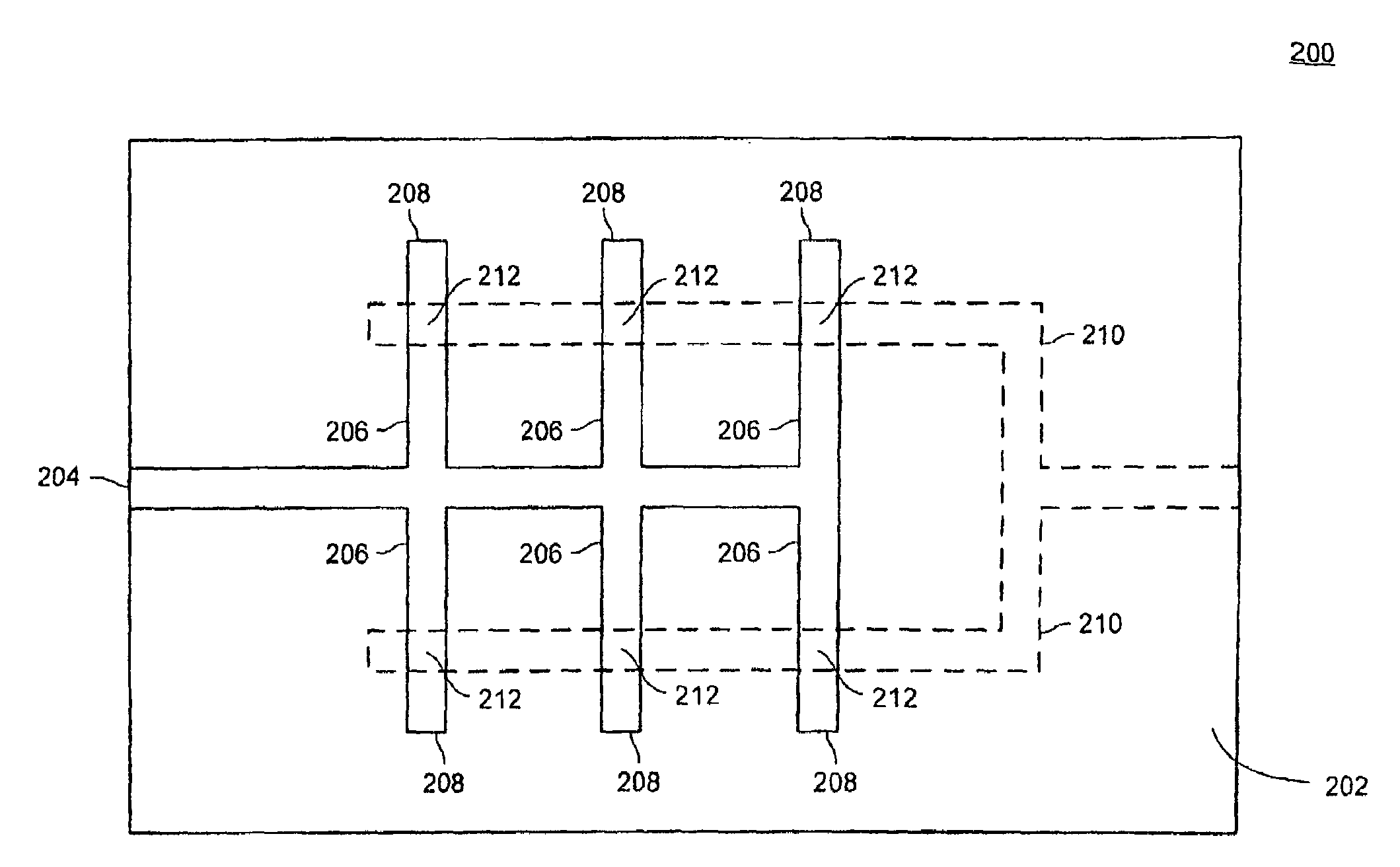
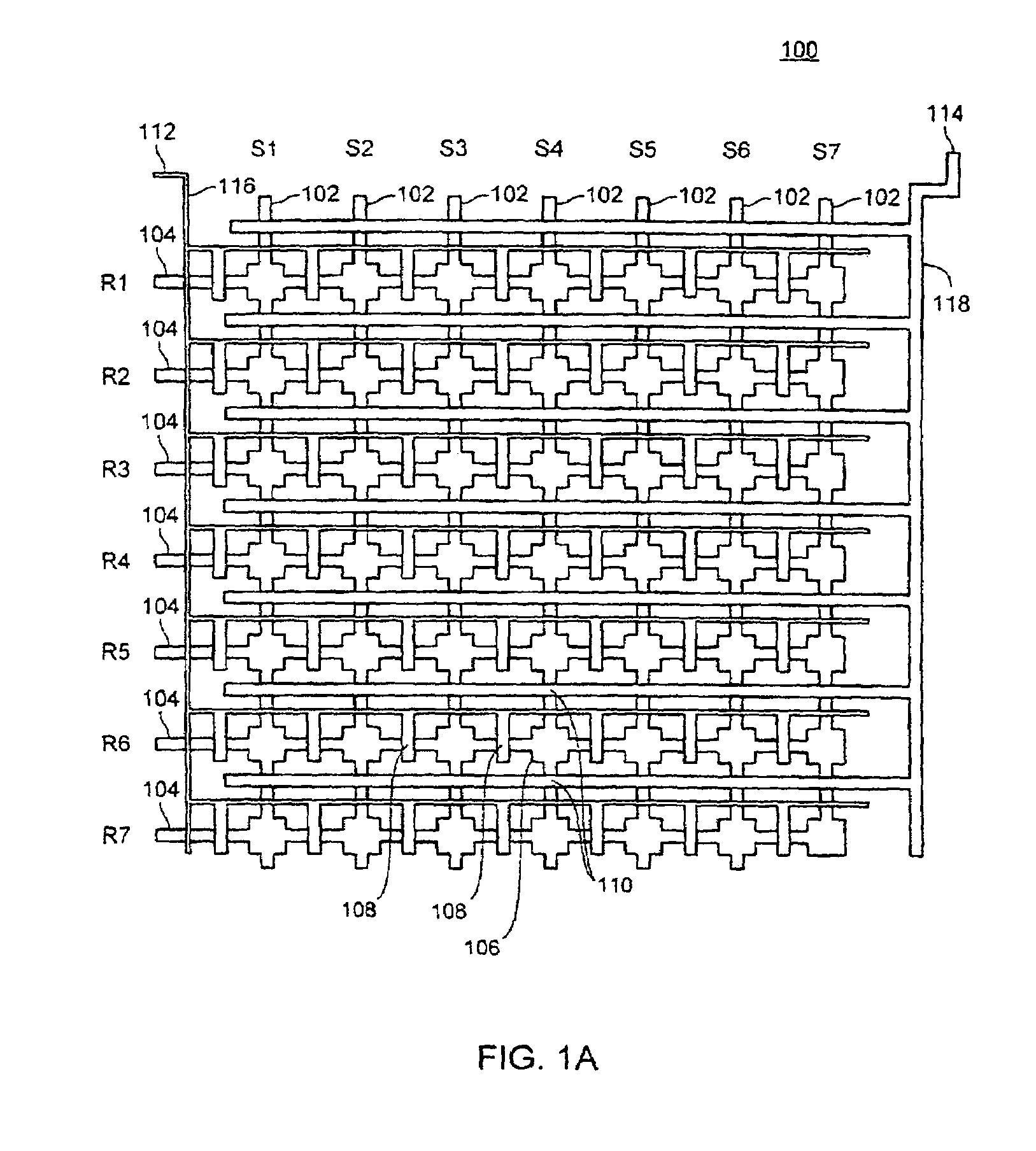
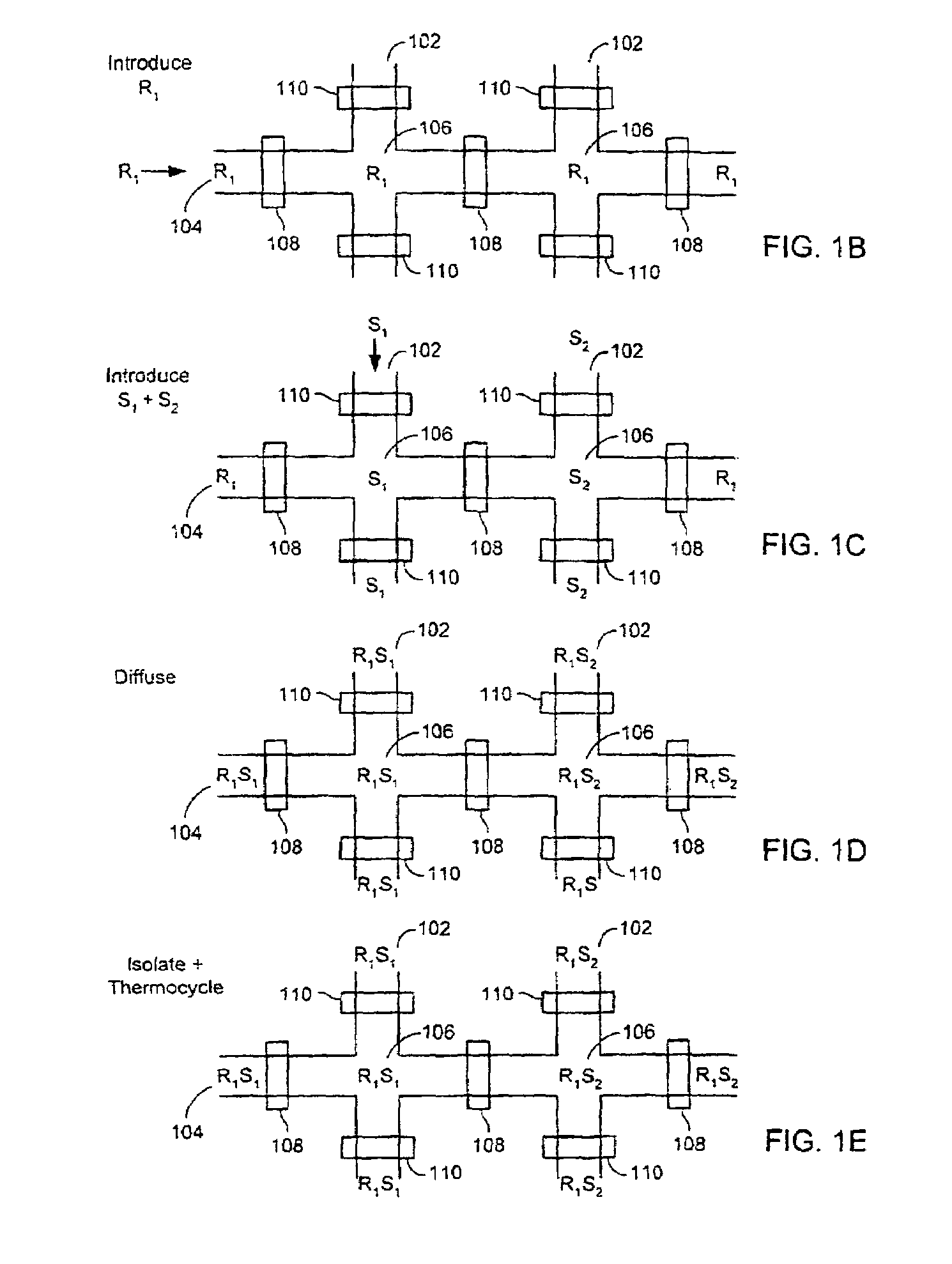
[0013]A variety of matrix or array-based devices are also provided. Certain of these devices include: (i) a first plurality of flow channels formed in an elastomeric substrate, (ii) a second plurality of flow channels formed in the elastomeric substrate that intersect the first plurality of flow channels to define an array of reaction sites, (iii) a plurality of isolation valves disposed within the first and second plurality of flow channels that can be actuated to isolate solution within each of the reaction sites from solution at other reaction sites, and (iv) a plurality of guard channels overlaying one or more of the flow channels and / or one or more of the reaction sites to prevent evaporation of solution therefrom.

Problems solved by technology

In other devices, however, the plurality of flow channels are isolated from each other such that fluid introduced into one flow channel cannot flow to another flow channel, and each flow channel comprises an inlet at one or both ends into which fluid can be introduced.

Method used


Image

  • Microfluidic devices and methods of using same
  • Microfluidic devices and methods of using same
  • Microfluidic devices and methods of using same

Examples


example 1

Signal Strength Evaluations

I. Introduction

[0214]The purpose of this set of experiments was to demonstrate that successful PCR reactions can be conducted with a microfluidic device of the design set forth herein with signal strength greater than 50% of the Macro TaqMan reaction.

II. Microfluidic Device

[0215]A three layer microfluidic device, fabricated using the MSL process, was designed and fabricated for conducting the experiments described in the following example. FIG. 7A shows a cross-sectional view of the device. As shown, the device 700 includes a layer 722 into which is formed the flow channels. This fluid layer 722 is sandwiched between an overlaying layer 720 that includes the control and guard layers and an underlying sealing layer 724. The sealing layer 724 forms one side of the flow channels. The resulting three-layer structure is affixed to a substrate 726 (in this example, a slide or coverslip), which provides structural stiffness, increases thermal conductivity, and he...

example 2

Spotting Reagents

I. Introduction

[0226]The purpose of the experiment was to demonstrate successful spotted PCR reactions in a microfluidic device. The term “spotted” in this context, refers to the placement of small droplets of reagents (spots) on a substrate that is then assembled to become part of a microfluidic device. The spotted reagents are generally a subset of the reagent mixture required for performing PCR.

II. Procedure

[0227]A. Spotting of Reagents

[0228]Routine spotting of reagents was performed via a contact printing process. Reagents were picked up from a set of source wells on metal pins, and deposited by contacting the pins to a target substrate. This printing process is further outlined in FIG. 9. As shown, reagents were picked up from a source (e.g., microtiter plates), and then printed by bringing the loaded pin into contact with the substrate. The wash step consists of agitation in deionized water followed by vacuum drying. The system used to print the reagent spots ...

example 3

Genotyping

I. Introduction

[0239]The purpose of the following experiments was to demonstrate that genotyping experiments can be conducted utilizing a microfluidic device or chip such as described herein. Specifically, these experiments were designed to determine if reactions conducted in the device have sufficient sensitivity and to ensure that other primer / probe sets, besidesβ-actin, can be performed in the microfluidic device.

II. Methods / Results

[0240]A. RNase P Experiment

[0241]RNase P TaqMan reactions (Applied Biosystems; Foster City, Calif.) were performed in a microfluidic device as described in Example 1 to demonstrate that other primer / probe sets produce detectable results. RNaseP reactions also require a higher level of sensitivity because the RNaseP primer / probe set detects a single copy gene (2 copies / genome) in contrast to the β-actin primer / probe set. The β-actin set detects a single copy β-actin gene and several pseudogenes, which collectively total approximately 17 copies...


PUM

PropertyMeasurementUnit
Pressureaaaaaaaaaa
Pressureaaaaaaaaaa
Pressureaaaaaaaaaa

Abstract

A variety of elastomeric-based microfluidic devices and methods for using and manufacturing such devices are provided. Certain of the devices have arrays of reaction sites to facilitate high throughput analyses. Some devices also include reaction sites located at the end of blind channels at which reagents have been previously deposited during manufacture. The reagents become suspended once sample is introduced into the reaction site. The devices can be utilized with a variety of heating devices and thus can be used in a variety of analyses requiring temperature control, including thermocycling applications such as nucleic acid amplification reactions, genotyping and gene expression analyses.

Description

PRIORITY CLAIM[0001]This non-provisional patent application claims priority under 35 U.S.C. §119(e) to U.S. Provisional Patent Application Ser. No. 60 / 460,634, filed on Apr. 3, 2003, by Unger et al., which is incorporated by reference in its entirety for all purposes and the specific purposes describe therein and herein.CROSS-REFERENCE TO RELATED APPLICATIONS[0002]This application relates to U.S. Non-Provisional application Ser. No. 10 / 306,798, filed on Nov. 27, 2002, which claims priority under 35 U.S.C. §119(e) to U.S. Provisional Application No. 60 / 391,529, filed Jun. 24, 2002, and of U.S. Provisional Application No. 60 / 335,292, filed Nov. 30, 2001, each of which is incorporated by reference in their entirety for all purposes.BACKGROUND[0003]Recently, there have been concerted efforts to develop and manufacture microfluidic systems to perform various chemical and biochemical analyses and syntheses, both for preparative and analytical applications. The goal to make such devices ar...

Claims


Application Information

Patent Timeline
IPC IPC(8): B01L3/00B01L3/02B01L7/00B01L99/00B81BC12Q1/68G01N1/10
CPCB01L3/5027B01L3/502723B01L3/502738B01L7/52B01L2200/0642B01L2200/142C12Q1/686B01L2300/0816B01L2300/0861B01L2300/123B01L2400/0481B01L2400/0638B01L2200/147B01L3/00
Inventor MCBRIDE, LINCOLNUNGER, MARCLUCERO, MICHAELNASSEF, HANY RAMEZFACER, GEOFFYI, YONG
Owner STANDARD BIOTOOLS INC
Learn More