Method for a burner and a corresponding device

a burner and burner technology, applied in the field of burners, can solve the problems of simple solution routes, inability to achieve particular effects, and practicable inability of people skilled in the art, and achieve the effect of less space and less drawbacks

Inactive Publication Date: 2010-02-23
SGL CARBON SE
View PDF20 Cites 22 Cited by
  • Summary
  • Abstract
  • Description
  • Claims
  • Application Information

AI Technical Summary

Benefits of technology

[0012]It is the object of the invention to improve a method and a device of the initially mentioned type in such manner that the thus developed apparatuses and / or burners occupy less space. In addition, a device is to be created for said method, by means of which it is possible for example, to perform the above-mentioned exothermal chemical reactions while lessening the drawbacks described in more detail above.
[0013]Based on the initially mentioned method, the object of the invention is solved in that prior to combustion, an additional gas is introduced, which does not significantly contribute to the combustion, such as an inert gas or water vapor or the exhaust gas from combustion or after-combustion, by means of which the temperature during combustion can be reduced to a value which is below the maximum temperature. In this respect, at least one additional supply line is provided for a device, by means of which an additional gas having an especially low combustion value, can be supplied, thus making it possible to reduce the temperature during combustion to a value below the maximum temperature.

Problems solved by technology

This simple route for solving the object, namely reducing the temperature with the aid of an additional gas, initially does not appear to be particularly effective.
With traditional measures, it also would have been practically unattainable by a person skilled in the art, that is to say, switching in parallel several low output hydrochloric acid synthesis plants in order to reduce the length.

Method used


Image

  • Method for a burner and a corresponding device
  • Method for a burner and a corresponding device
  • Method for a burner and a corresponding device

Examples


example 1

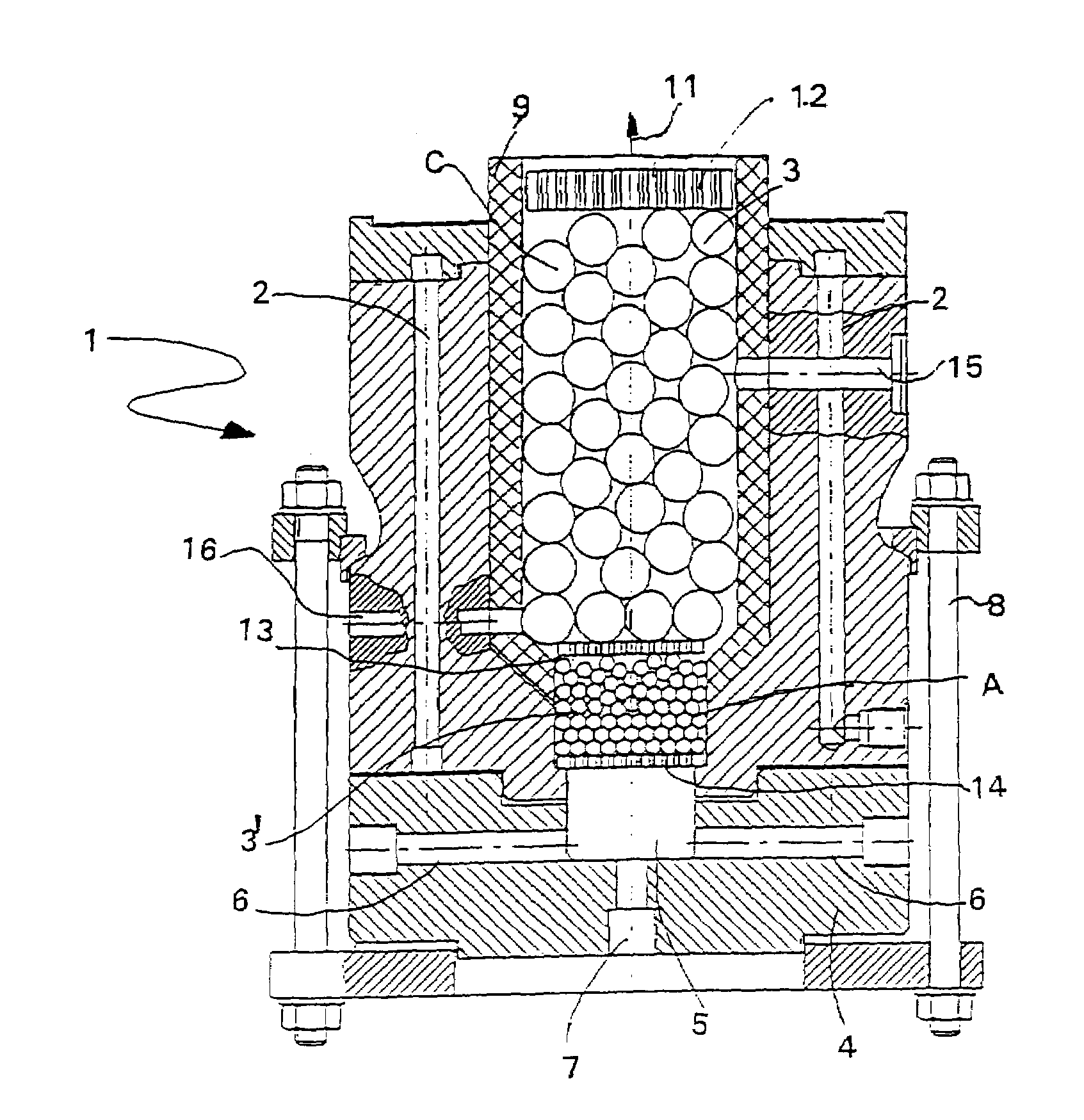
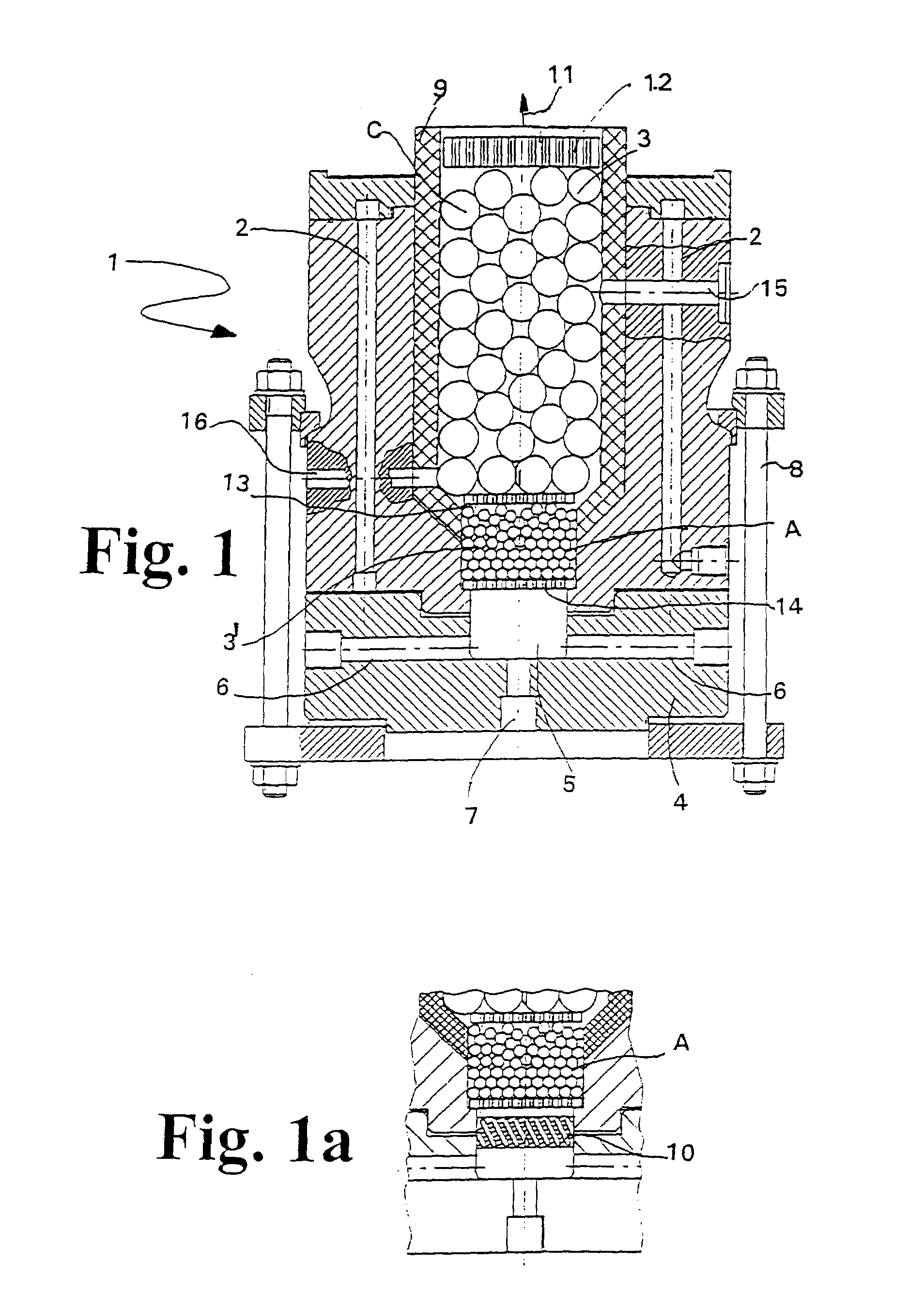
[0116]Hydrochloric acid was produced from hydrogen (1.12 m3 / h) and chlorine (1.09 m3 / h) with a pore burner 1 according to FIG. 1. In a process-engineered pilot plant according to FIG. 5. a stream of inert gas stream was blown in as added gas for lowering the flame temperature, also 0.73 kg / h of steam was added into the pre-mix chamber. With a stoichiometric hydrogen surplus of 3%, a free chlorine contents of less than 3% was ascertained in the 30% (by weight) hydrochloric acid, which was produced by combustion.

example 2

[0117]An exhaust gas containing methyl-chloride was subjected to post-combustion in a pore burner 1 according to FIG. 5, in a plant according to FIG. 7, in a support flame of 0.17 m3 natural gas and 1.54 m3 / h air. A post-combustion gas with approximately 0.1% methyl chloride in air was introduced as exhaust gas with 0.35 m3 / h. The temperature of the exhaust gas escaping from the pore burner was at approximately 1100° C. The contents of methyl chloride in the exhaust gas was less than 12 ppm.

example 3

[0118]The following results were obtained in a test using a plant according to FIG. 6 and a pore burner according to FIG. 1: Combustion of 0.12 m3 / h chlorine with 0.2 m3 / h natural gas (methane) and 2.8 m3 / h air. Hydrochloric acid (30%) free from carbon black was produced. Contents of carbon mono-oxide was smaller than 0.5%. By-products such as polychlorinated dioxins and furans could not be ascertained in the acid nor in the exhaust gas. Chlorine contents in the acid was less than 50 ppm.

[0119]Subject to unfavorable parameters, the exhaust gas with high air excess could once more be subjected to after-combustion in a device according to FIG. 5.


PUM

PropertyMeasurementUnit
combustion temperatureaaaaaaaaaa
lengthaaaaaaaaaa
sizeaaaaaaaaaa

Abstract

The invention relates to a device equipped with a burner for combusting a fuel / oxidant mixture inside a combustion chamber in which a material (3, 3′, 3″, 3′″) is provided that endures a maximum temperature. The inventive device also comprises one or more supply lines (25, 26) for the fuel as well as for the oxidant which are provided for supplying the same into the combustion chamber. The inventive device is characterized in that it is designed for carrying out a combustion with a combustion temperature of the fuel / oxidant mixture that exceeds the maximum temperature. The device is designed in such a way that at least one additional supply line (30) is provided via which an additional gas having, in particular, a low calorific value can be supplied to the combustion chamber. Said additional gas enables the temperature during combustion to be lowered to a value that is less than the maximum temperature.

Description

FIELD OF INVENTION[0001]The invention relates to a method for a burner for combustion of a fuel / oxidant mixture within a combustion chamber, in which a material is provided which endures a maximum temperature, said temperature being lower than the combustion temperature of the fuel / oxidant mixture. The invention further relates to a device with a burner for combustion of a fuel / oxidant mixture within a combustion chamber, in which a material is provided which endures a maximum temperature, with one or several supply lines for the fuel and for the oxidant, in order to introduce these into the combustion chamber. In addition, the invention relates to applications for the method and / or applications of the device.BACKGROUND OF INVENTION[0002]It is the goal of most burner applications to attain, among others, the most effective combustion possible in order to achieve the maximum degree of efficiency. However, the temperature limit is usually restricted by the temperature resistance of th...

Claims


Application Information

Patent Timeline
Patent Type & Authority Patents(United States)
IPC IPC(8): B01J19/00F23D14/02F23D14/12B01D53/34B01J8/04C01B7/01C01B7/07F23C99/00F23L7/00
CPCB01D53/34C01B7/01C01B7/012C01B7/0737F23C99/006F23D14/02F23L7/00B01J8/0426F23L2900/07009B01J2208/00061B01J2208/00132B01J2208/00256B01J2208/00274B01J2208/00513B01J2219/00263B01J2219/0272F23L2900/07002
Inventor DURST, FRANZKUNZEL, JURGEN
Owner SGL CARBON SE
Why Eureka
Try Eureka