Fuel cell and fuel cell stack with pressure chambers

a fuel cell and stack technology, applied in the field of fuel cells, can solve the problems of inability to achieve the desired stress absorption function, uneven surface pressure in the current collector, undetected damage to the electrode assembly, etc., and achieve the effect of simple and compact structur

Inactive Publication Date: 2010-03-02
HONDA MOTOR CO LTD
View PDF13 Cites 4 Cited by
  • Summary
  • Abstract
  • Description
  • Claims
  • Application Information

AI Technical Summary

Benefits of technology

[0012]A general object of the present invention is to provide a fuel cell and a fuel cell stack having a simple and compact structure in which the uniform surface pressure between an electrolyte electrode assembly and a current collector is maintained, and flows of reactant gas or the like are uniform.
[0022]Therefore, dimensional variations of the separator and the electrolyte electrode assembly are absorbed. With the simple and compact structure, it is possible to maintain the uniform surface pressure applied between the electrolyte electrode assembly and the first and second plates as the current collectors. Further, the current collectors tightly contact the entire surfaces of the electrodes of the electrolyte electrode assembly with the uniform surface pressure. The contact resistances of the current collectors are reduced. Thus, improvement in the power generation efficiency is achieved easily.
[0024]Moreover, uniform shapes of the respective fluid passages formed between the electrolyte electrode assembly and current collectors are maintained. Thus, the flows of the reactant gases or the like are uniform, and improvement in the power generation efficiency is achieved.

Problems solved by technology

In particular, since the rigidity of the current collector is high, the electrolyte electrode assembly may be damaged undesirably.
Thus, the surface pressure in the current collector is not uniform.
Thus, the desired stress absorption function may not be achieved.
Further, deformation of the metal thin plates 7 due to the change in the elasticity would result in the non-uniform shapes of the respective fluid passages.
In this case, it is difficult to achieve the uniform flows of the reactant gases or the like.

Method used


Image

  • Fuel cell and fuel cell stack with pressure chambers
  • Fuel cell and fuel cell stack with pressure chambers
  • Fuel cell and fuel cell stack with pressure chambers

Examples


first embodiment

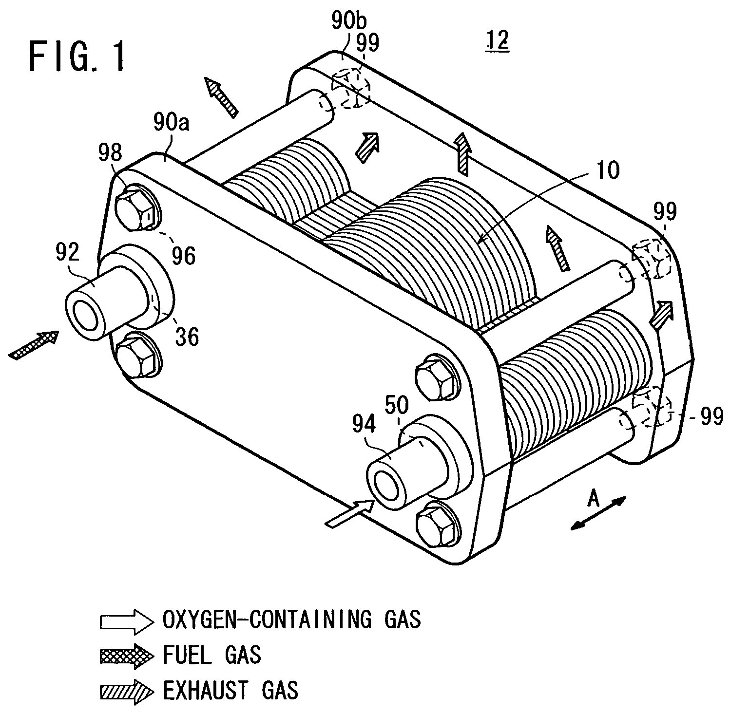
[0047]FIG. 1 is a perspective view schematically showing a fuel cell stack 12 formed by stacking a plurality of fuel cells 10 according to the present invention in a direction indicated by an arrow A.

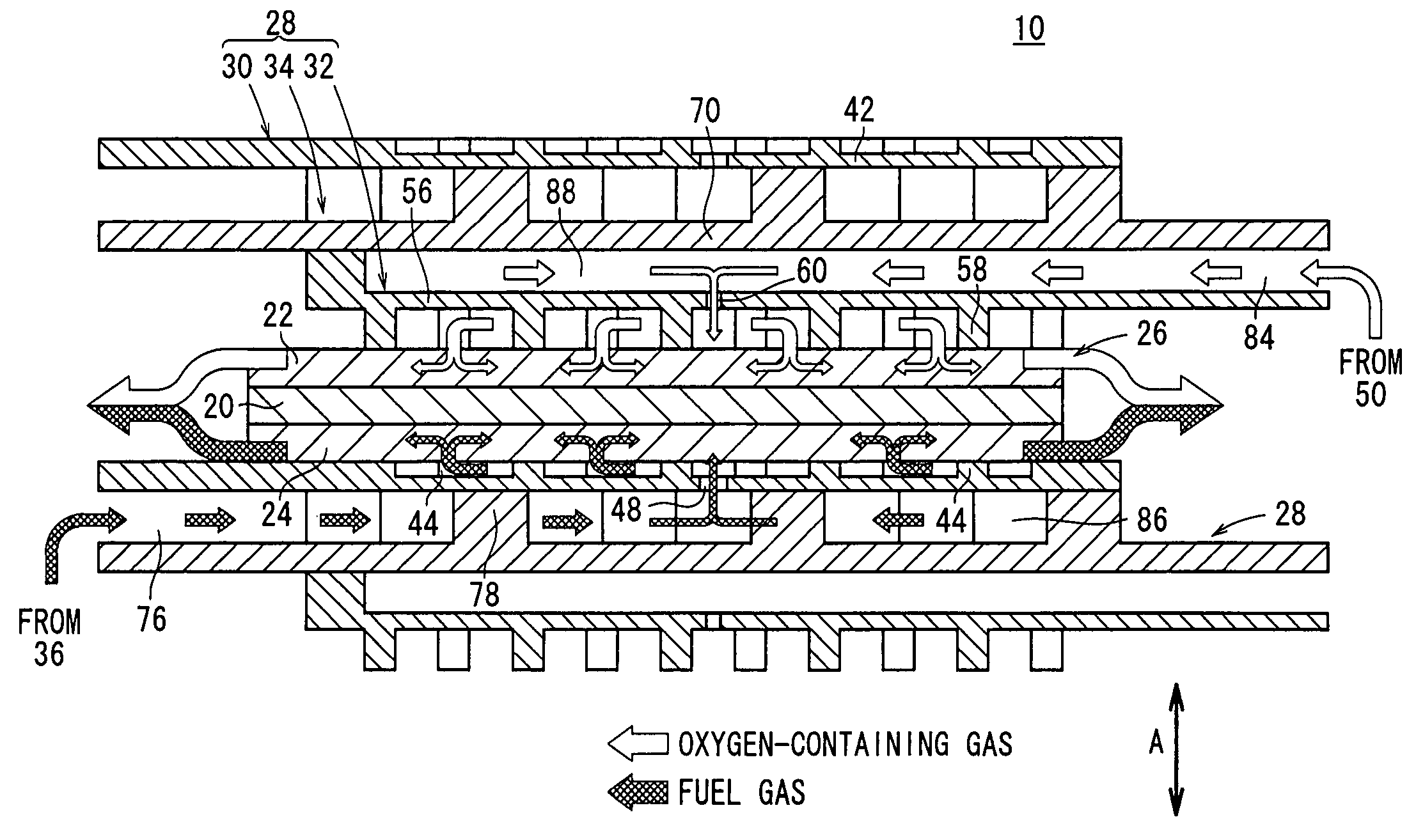
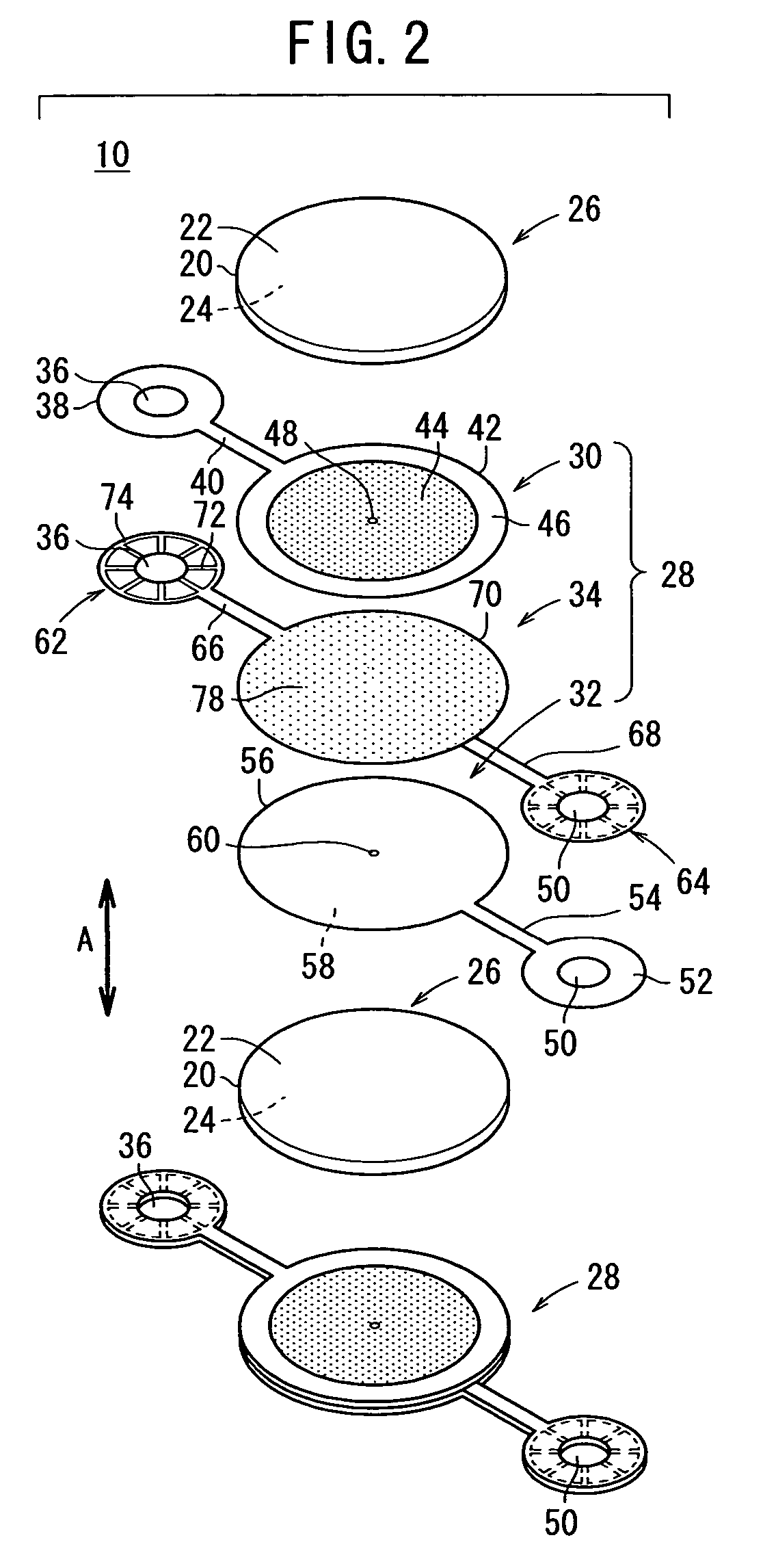
[0048]The fuel cell 10 is a solid oxide fuel cell (SOFC) used in various applications, including stationary and mobile applications. The fuel cell 10 is mounted on a vehicle. As shown in FIGS. 2 and 3, the fuel cell 10 includes an electrolyte electrode assembly 26. The electrolyte electrode assembly 26 includes a cathode 22, an anode 24, and an electrolyte (electrolyte plate) 20 interposed between the cathode 22 and the anode 24. For example, the electrolyte 20 is made of ion-conductive solid oxide such as stabilized zirconia. The electrolyte electrode assembly 26 has a circular disk shape.

[0049]The fuel cell 10 is formed by sandwiching the electrolyte electrode assembly 26 between a pair of separators 28. The separator 28 includes first and second plates 30, 32, and a third plate 34 in...

second embodiment

[0080]FIG. 10 is a perspective view schematically showing a fuel cell stack 102 formed by stacking a plurality of fuel cells 100 according to the present invention in a direction indicated by an arrow A. FIG. 11 is a cross sectional view showing part of a fuel cell system 106 in which the fuel cell stack 102 is disposed in a casing 104.

[0081]The constituent elements that are identical to those of the fuel cell 10 according to the first embodiment are labeled with the same reference numeral, and description thereof will be omitted. In a third embodiment as described later, the constituent elements that are identical to those of the fuel cell 10 according to the first embodiment are labeled with the same reference numeral, and description thereof will be omitted.

[0082]As shown in FIGS. 12 and 13, a plurality of, e.g., eight electrolyte electrode assemblies 26 are interposed between a pair of separators 108 to form the fuel cell 100. The electrolyte electrode assemblies 26 are concentr...

third embodiment

[0118]FIG. 18 is a perspective view schematically showing a fuel cell stack 202 formed by stacking a plurality of fuel cells 200 according to the present invention in a direction indicated by an arrow A. FIG. 19 is an exploded perspective view showing the fuel cell 200.

[0119]The fuel dell 200 includes a plurality of, e.g., fifteen electrolyte electrode assemblies 26 between a pair of separators 208. Each of the separators 208 includes first and second plates 210, 212 which are stacked together, and a third plate 214 interposed between the first and second plates 210, 212. The first through third plates 210, 212, and 214 are metal plates of, e.g., stainless alloy.

[0120]The first plate 210 has a first small diameter end portion 215. The fuel gas supply passage 36 extends through the first small diameter end portion 215. The first small diameter end portion 215 is integral with first circular disks 218 through a narrow bridge 216. The first circular disks 218 are arranged in directions...


PUM

PropertyMeasurementUnit
internal pressureaaaaaaaaaa
pressureaaaaaaaaaa
electric energyaaaaaaaaaa

Abstract

A fuel cell includes an electrolyte electrode assembly and separators. The separator includes first through third plates which are stacked together. A fuel gas channel connected to a fuel gas supply passage is formed between the first and third plates. The fuel gas channel forms a fuel gas pressure chamber between the first and third circular disks. Further, an oxygen-containing gas channel connected to an oxygen-containing gas supply passage is formed between the second and third plates. The oxygen-containing gas channel forms an oxygen-containing gas pressure chamber between the second and third circular disks.

Description

BACKGROUND OF THE INVENTION[0001]1. Field of the Invention[0002]The present invention relates to a fuel cell formed by stacking an electrolyte electrode assembly and separators alternately. The electrolyte electrode assembly includes an anode, a cathode, and an electrolyte interposed between the anode and the cathode. Further, the present invention relates to a fuel cell stack formed by stacking the fuel cells.[0003]2. Description of the Related Art[0004]Typically, a solid oxide fuel cell (SOFC) employs an electrolyte of ion-conductive solid oxide such as stabilized zirconia. The electrolyte is interposed between an anode and a cathode to form an electrolyte electrode assembly (unit cell). The electrolyte electrode assembly is interposed between separators (bipolar plates). In use, a predetermined numbers of the unit cells and the separators are stacked together to form a fuel cell stack.[0005]In the fuel cell, an oxygen-containing gas or air is supplied to the cathode. The oxygen i...

Claims


Application Information

Patent Timeline
Patent Type & Authority Patents(United States)
IPC IPC(8): H01M2/14H01M2/00H01M8/00H01M8/10H01M8/02H01M8/04H01M8/12H01M8/24
CPCH01M8/0228H01M8/0247H01M8/025H01M8/0297H01M8/04089H01M8/2425H01M8/0254H01M2008/1293Y02E60/50Y02E60/525H01M8/2432H01M8/2457H01M8/24H01M8/02H01M8/12H01M8/243
Inventor TSUNODA, TADASHI
Owner HONDA MOTOR CO LTD
Why Eureka
Try Eureka