
Methods and apparatus for scan block caching

a scan block and cache technology, applied in the field of methods, can solve the problems of not being applicable to video and digital graphics, none of the compression algorithms that take advantage of the recurring history pattern, and the power of personal computers, etc., to achieve the effect of efficient transmission of graphic display signals, reducing the required bandwidth and resulting latency of a remote display, and high probability of re-us

Active Publication Date: 2010-03-02
TERADICI CORP
View PDF7 Cites 82 Cited by
  • Summary
  • Abstract
  • Description
  • Claims
  • Application Information

AI Technical Summary

Benefits of technology

[0014]The primary objective of the present invention is to provide a method and apparatus for efficiently transmitting a graphic display signal from a host data processing system to a remote display across a communications link. Another objective of the present invention is to provide a method and apparatus for reducing the required bandwidth and resulting latency of a remote display by maintaining a synchronized cache of scan blocks that have a high probability of re-use at the remote display. A further objective of the invention is to provide a non-intrusive system capable of acquiring the graphic display signal produced by a host computing system and to transfer the signal to a remote display as a data stream.
[0016]In another aspect, the present invention provides a method for determining the probability of re-use of a scan block and synchronizing the image cache at a remote display based on that probability. The method includes testing for the history or persistence of an incoming scan block; storing a hash code associated with a persistent scan block in a history hash table; instructing the remote display to store the actual scan block in its local cache; and applying cache update and replacement policies to the history scan hash table to optimize the likelihood of positive history table hits.

Problems solved by technology

Continued advances of this computer technology have made these personal computers very powerful but also complex and difficult to manage.
While there are a variety of techniques used today to communicate video or graphics across a network of limited bandwidth, none utilize compression algorithms that take advantage of the recurring history patterns found within a computer display image.
One of the challenges associated with existing techniques lies in the development of methods capable of transmitting high bandwidth display signals from the processing components to the remote desktop across a standard network of relatively low bandwidth.
Additionally, these methods are not applicable to video and digital graphics.
This is impractical for sending a normal SXGA display image of 1280×1024 at 24-bit color resolution across a standard 100 Base T LAN network as each 4 MB frame would take 0.3 seconds of dedicated network bandwidth, making perception-free communications of display information impossible.
This method is both restrictive in its compatibility and intrusive as it requires operating system dependent graphic command routing software running on the data processor.
This adds cost and complexity to the remote installation.
This decreases the overall amount of data, especially for computer displays where much of the display is often static from frame to frame.
This approach is expensive to implement as the data processor requires at least two frame buffers, a copy of the previously communicated frame buffer and the present frame.
This approach is memory- and computationally intensive, thus decreasing the performance of applications running on the data processor.
These tiling and list systems and methods are limited.
Any copying of display pixels or signatures loads the system bus of the data processor, lowering the performance of the system.
Some of the methods interrupt the operating system for a background task to manage the activity, which severely reduces the performance of the data processor.
In summary, existing methods of transferring display information from a data processor to a remote user interface are limited by high cost and high maintenance requirements.
The supported display update rates are low or the methods used adversely impact the performance of the data processor.
None of the systems described take advantage of the specific characteristics of a computer display, specifically the frequent transitions of parts of a display image to historic, previously-displayed states.
None of these methods use a non-intrusive compression engine capable of perception-free, real-time compression of a digital raster signal.

Method used


Image

  • Methods and apparatus for scan block caching
  • Methods and apparatus for scan block caching
  • Methods and apparatus for scan block caching

Examples


Embodiment Construction

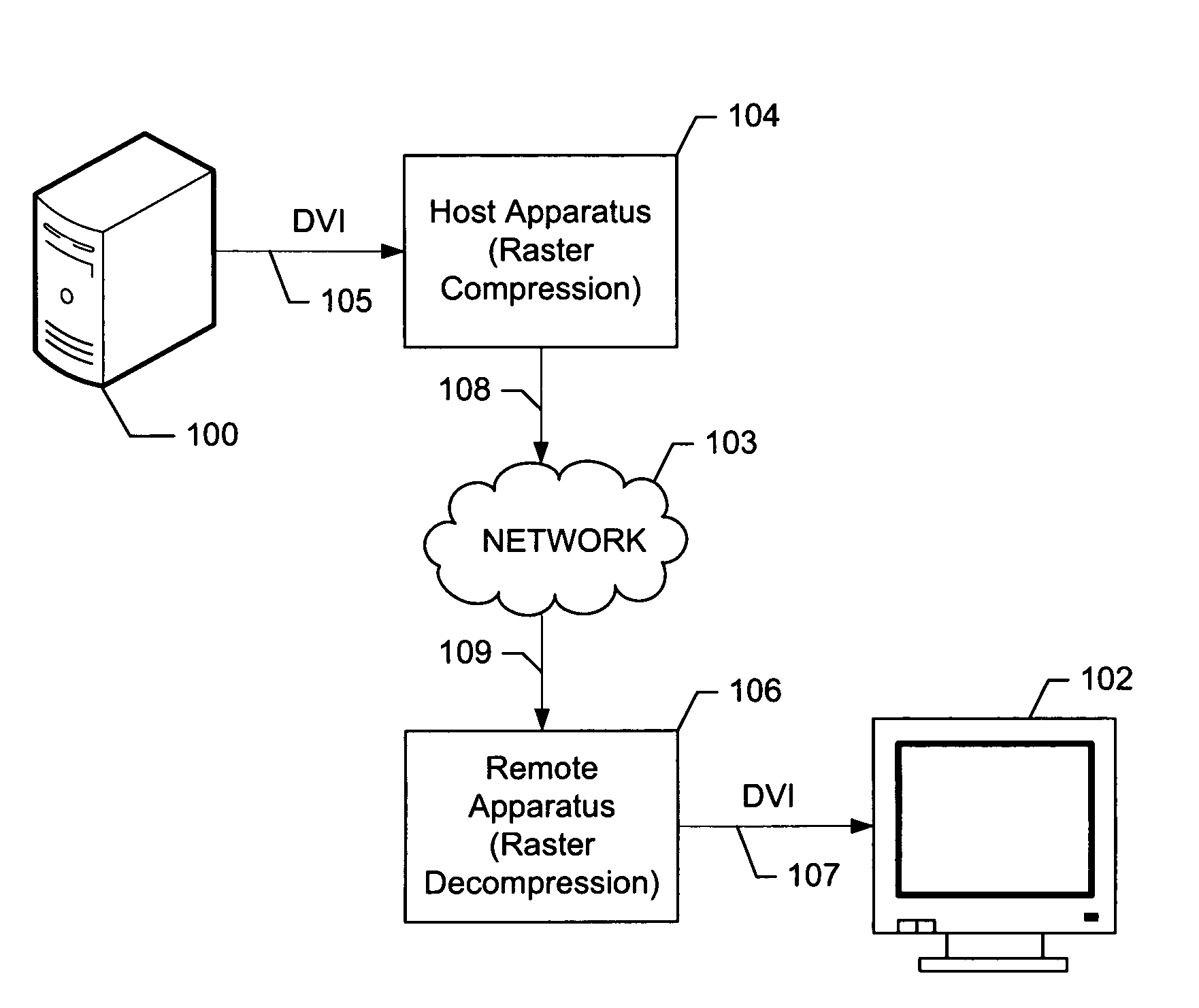
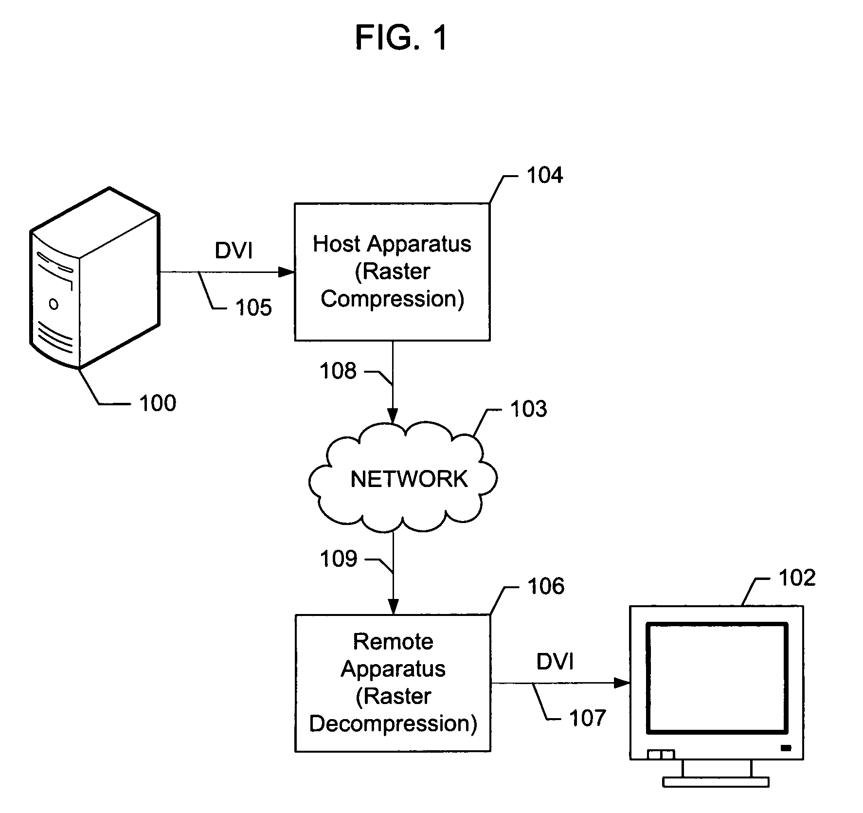
[0025]FIG. 1 provides a system-level illustration showing the context of the invention. A data processing system 100 is connected to a remote display 102 via a transmission network 103. The invention itself is comprised of two components inserted in the communications path between data processing system 100 and remote display 102. The first component is raster compression apparatus 104 that connects to display output signal 105 of data processing system 100 and is located at the data processing side of network 103. This component is referred to herein as the “host apparatus.” The second component is raster decompression apparatus 106 that connects to display input signal 107 of remote display 102 and is located at the remote display end of network 102. This component is referred to herein as the “remote apparatus.”

[0026]In the preferred embodiment, display output signal 105 from data processing system 100 is a Digital Visual Interface (DVI) digitized raster signal. In alternative em...


PUM


Abstract

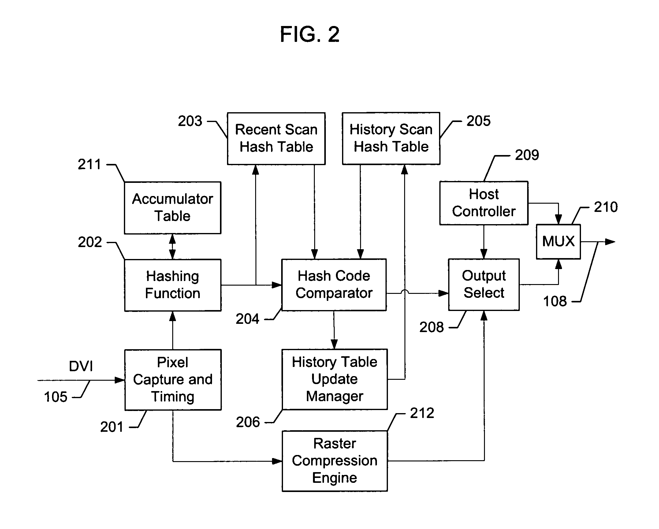
A method and apparatus for comparing portions of data from a digital raster signal to a plurality of scan blocks of data, where each scan block in the plurality describes either a defined image area or entire image frame is disclosed. Included are a hashing function that calculates hash codes for spatially-defined segments of an incoming raster signal; a recent scan hash table containing hash codes for scan blocks received within a specified time period; a comparator for comparing calculated hash codes for the spatially-defined segments of the incoming raster signal with hash codes stored in the recent scan hash table; a pixel capture and timing module for capturing a digital raster signal; and an output selector for selecting for transmission a compressed form of a scan block, a hash code index, or no data if a scan block exists in a remote frame playout buffer.

Description

RELATED APPLICATION[0001]This application claims priority to U.S. Provisional Application Ser. No. 60 / 584,751, entitled “Method and Apparatus for Screen Block Caching for Remote Graphical Display,” filed Jun. 30, 2004, incorporated by reference herein in its entirety.FIELD OF THE INVENTION[0002]The invention relates generally to a method for communicating graphics signals across a transmission medium and more particularity to a method for transmitting a computer display signal to a remote user interface across a standard network.BACKGROUND OF THE INVENTION[0003]Historic advances in computer technology have made it economical for individual users to have their own computing system, which caused the proliferation of the Personal Computer (PC). Continued advances of this computer technology have made these personal computers very powerful but also complex and difficult to manage. For this and other reasons, there is a desire in many workplace environments to separate the user interface...

Claims


Application Information

Patent Timeline
Patent Type & Authority Patents(United States)
IPC IPC(8): G06F15/00G06F12/02
CPCH04N1/41
Inventor HOBBS, DAVID V.LIN, BILL
Owner TERADICI CORP
Learn More