OFDM receiving method and apparatus
a receiving method and receiving device technology, applied in the field of receiving devices and receiving devices, can solve the problems of reducing the guard interval at the same time, affecting the transmission efficiency of the receiving side, so as to achieve the effect of improving upon performance degradation and without loss of transmission efficiency
- Summary
- Abstract
- Description
- Claims
- Application Information
AI Technical Summary
Benefits of technology
Problems solved by technology
Method used
Image
Examples
first embodiment
(B) First Embodiment
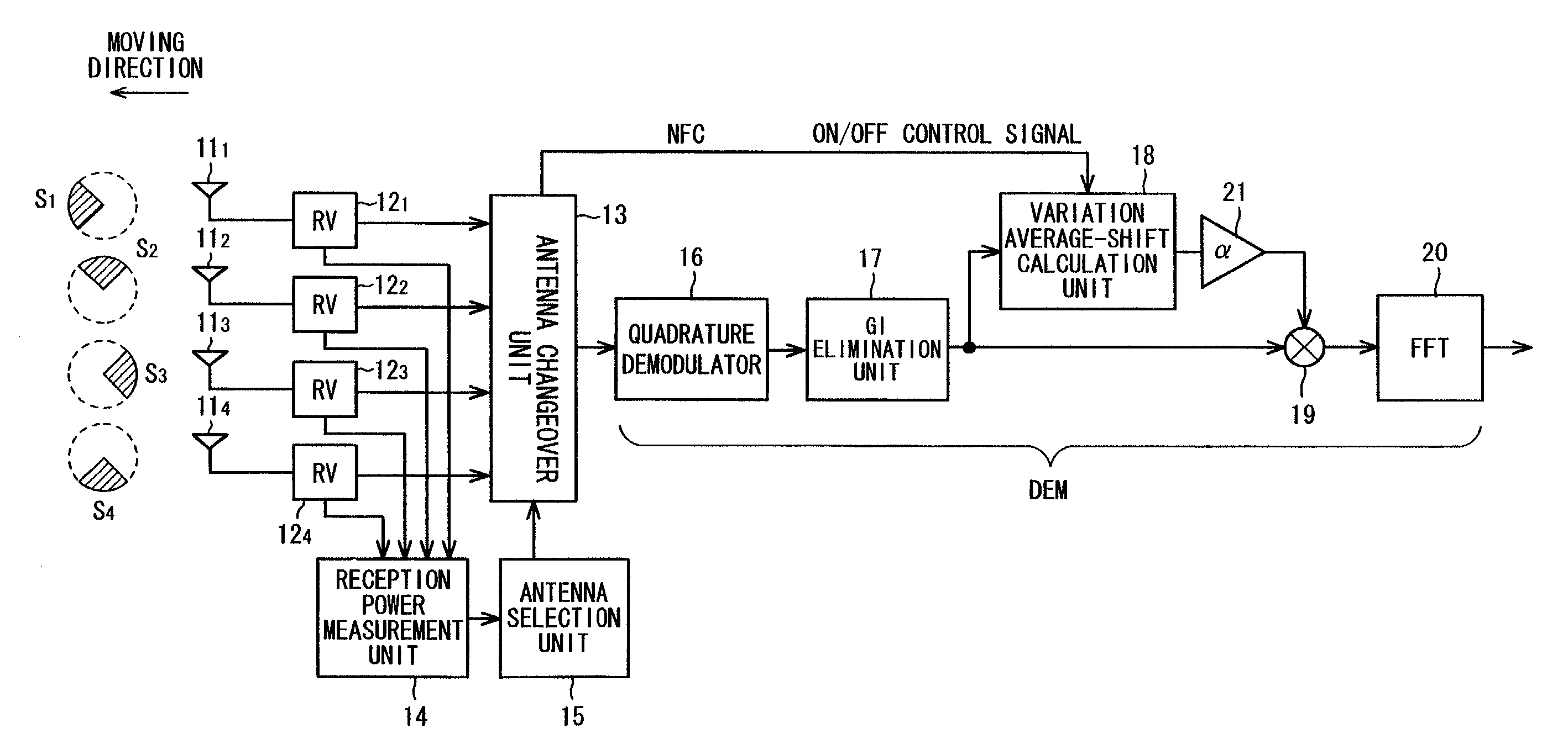
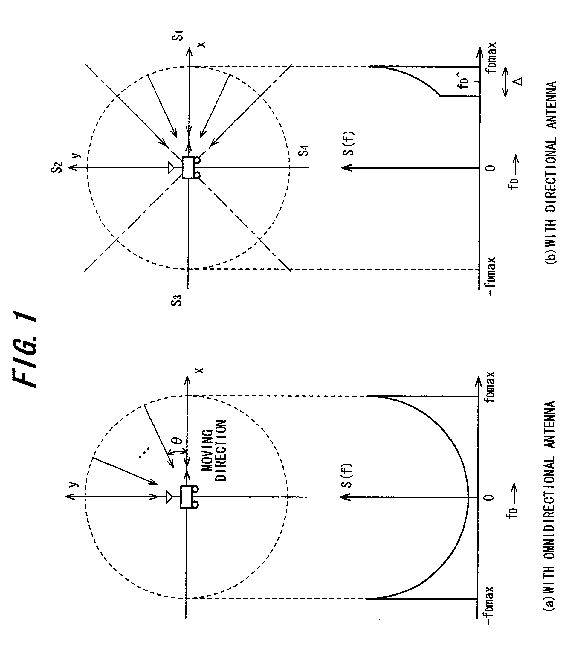
[0057]FIG. 7 is a block diagram of an OFDM receiving apparatus according to the present invention. An angle of 360° centered on an automotive vehicle serving as a mobile body is divided into four sectors of 90° each indicated by S1 to S4 in (b) of FIG. 1, and the sectors S1 to S4 are provided with directional antennas 111 to 114, respectively. Sector S1 points forward in the direction of vehicular movement, sector S4 points rearward away from the direction of moving, and the remaining sectors S2, S3 point right and left, respectively, with respect to the direction of moving. Radio receivers 121 to 124 amplify received radio signals from respective ones of the antennas, effect a frequency down-conversion to baseband signals and input these signals to an antenna changeover unit 13. A reception power measurement unit 14 measures reception power by measuring the reception signal strengths, e.g., the RSSI (Received Signal Strength Indicators), of the radio receivers 1...
third embodiment
(E) Third Embodiment
[0066]In a case where a plurality of fixed beam patterns are used (e.g., in the case of a switched beam or sector antenna), it is necessary to select a directional antenna whose directivity is in the direction of moving in order to suppress ICI. Since an object of the present invention is to suppress ICI, a directional antenna is selected according to a criterion different from that used in improving power efficiency (i.e., in increasing the S / N ratio by raising antenna gain in the direction along which radio waves arrive), which is the inherently merit of a directional antenna. In other words, with the conventional scheme, a directional antenna having directivity in the direction along which radio waves are arrive, e.g., an antenna for which reception power is highest among a plurality of directional antennas, is selected. In the present invention, however, a directional antenna must be selected in such a manner that ICI can be suppressed. For this reason, there...
fourth embodiment
(F) Fourth Embodiment
[0074]As pointed out above, ICI is proportional to moving velocity (v). That is, if moving velocity is high, the Doppler frequency fDmax increases, the Doppler spectrum spreads and ICI increases, as shown in (a) of FIG. 15. However, if moving velocity is low, the Doppler frequency fDmax decreases, the Doppler spectrum narrows and ICI decreases, as shown in (b) of FIG. 15. Further, since the present invention does not use a directional antenna in the conventional manner of use, it cannot be said that the first to third embodiments are always the optimum arrangements in a range wherein ICI has no influence upon reception performances, namely when the mobile body is moving at low velocity. The reason for this is that since a directional antenna is used, reception power that is capable of being received by an omnidirectional antenna is partially lost in an environment where radio waves arrive uniformly.
[0075]FIG. 16 is a block diagram of an OFDM receiving apparatus ...
PUM
 Abstract
Description
Claims
Application Information
 - R&D
- Intellectual Property
- Life Sciences
- Materials
- Tech Scout
- Unparalleled Data Quality
- Higher Quality Content
- 60% Fewer Hallucinations
Browse by: Latest US Patents, China's latest patents, Technical Efficacy Thesaurus, Application Domain, Technology Topic, Popular Technical Reports.
© 2025 PatSnap. All rights reserved.Legal|Privacy policy|Modern Slavery Act Transparency Statement|Sitemap|About US| Contact US: help@patsnap.com


