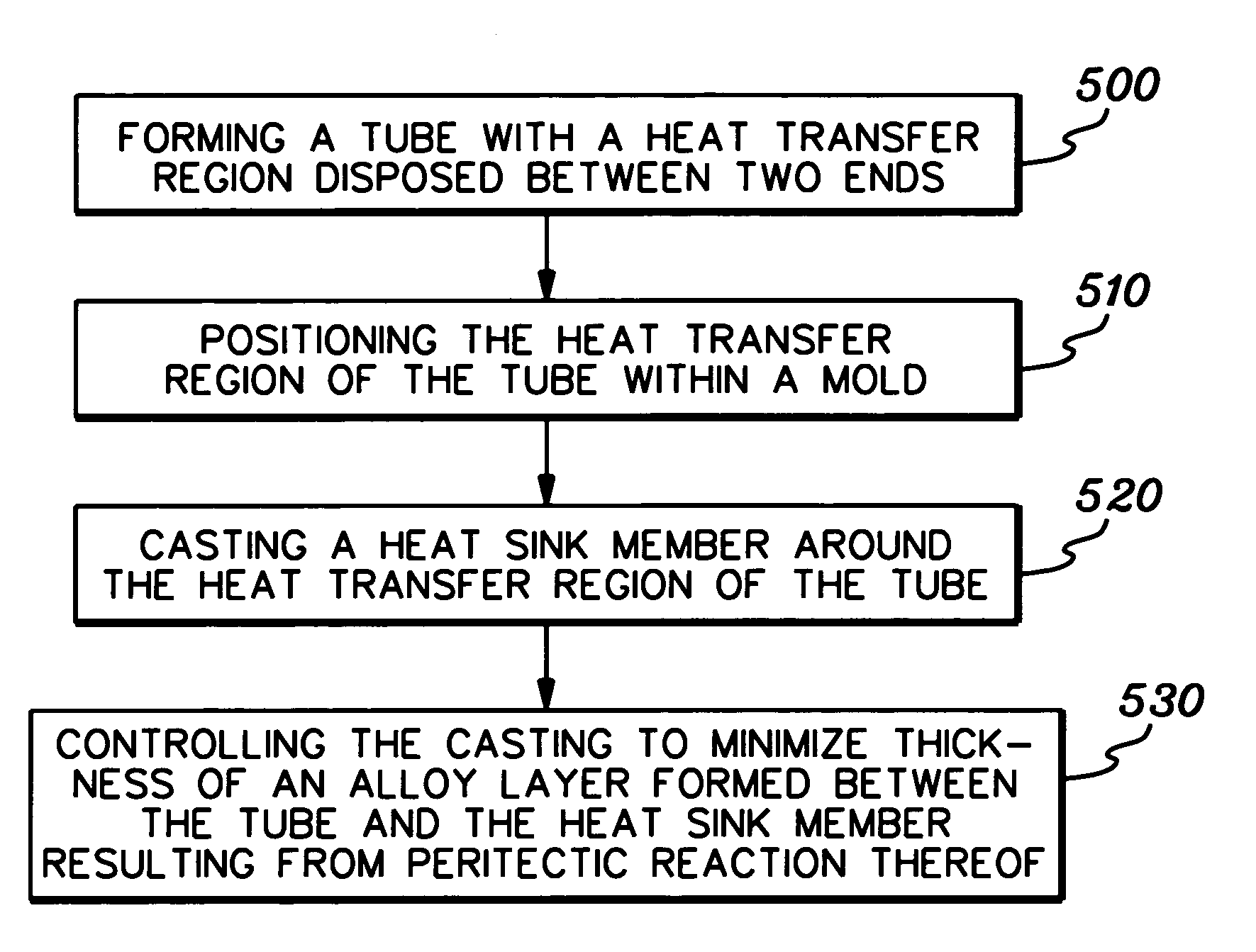
Cold plate apparatus and method of fabrication thereof with a controlled heat transfer characteristic between a metallurgically bonded tube and heat sink for facilitating cooling of an electronics component
a technology of heat transfer characteristic and heat sink, which is applied in the direction of electrical apparatus construction details, light and heating apparatus, laminated elements, etc., can solve the problems of inability to achieve practical approaches, and achieve the effects of good thermal conductor, good thermal conductor, and limited corrosion
- Summary
- Abstract
- Description
- Claims
- Application Information
AI Technical Summary
Benefits of technology
Problems solved by technology
Method used
Image

Examples
Embodiment Construction
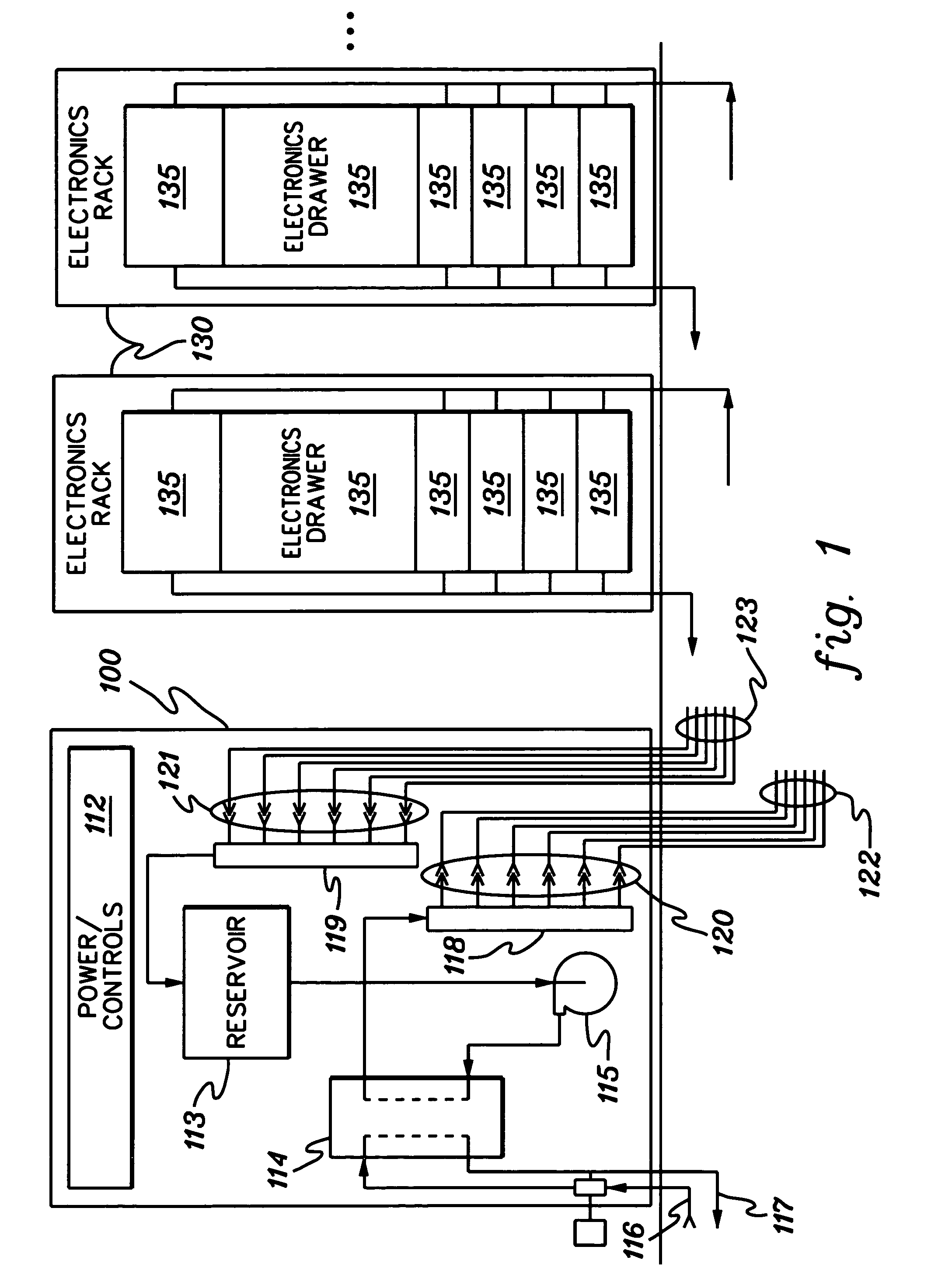
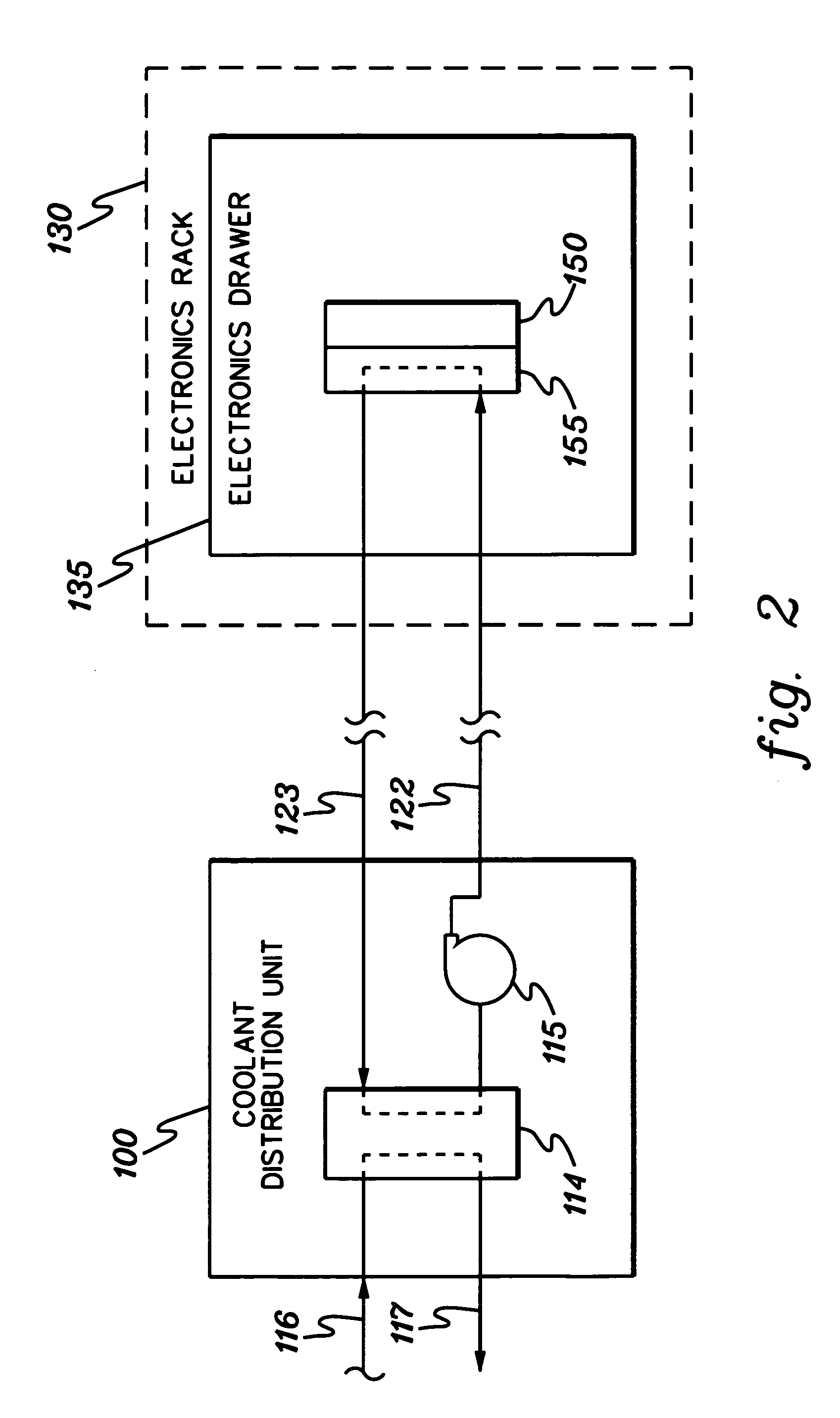
[0021]As used herein, “electronics subsystem” comprises any housing, compartment, drawer, blade, etc., containing one or more heat generating components of a computer system or other electronics system requiring cooling. The term “electronics rack” includes any frame, rack, blade server system, etc., having a heat generating component of a computer system or electronics system, and may be, for example, a stand alone computer processor having high, mid or low end processing capability. In one embodiment, an electronics rack may comprise multiple electronics subsystems, each having one or more heat generating electronics components requiring cooling. Each “heat generating electronics component” may comprise an electronic device, an electronics module, an integrated circuit chip, etc.
[0022]One example of coolant within a cooling system in accordance with an aspect of the present invention is water. However, the concepts disclosed herein are readily adapted to use with other types of co...
PUM
| Property | Measurement | Unit |
|---|---|---|
| temperature | aaaaa | aaaaa |
| temperature | aaaaa | aaaaa |
| diameter | aaaaa | aaaaa |
Abstract
Description
Claims
Application Information
 - R&D
- Intellectual Property
- Life Sciences
- Materials
- Tech Scout
- Unparalleled Data Quality
- Higher Quality Content
- 60% Fewer Hallucinations
Browse by: Latest US Patents, China's latest patents, Technical Efficacy Thesaurus, Application Domain, Technology Topic, Popular Technical Reports.
© 2025 PatSnap. All rights reserved.Legal|Privacy policy|Modern Slavery Act Transparency Statement|Sitemap|About US| Contact US: help@patsnap.com