LED projector light module

a projector light and module technology, applied in semiconductor devices, lighting and heating apparatus, semiconductor devices for light sources, etc., can solve the problems of high heat generation, halogen light bulbs consume considerable electricity, and tend to get hot, so as to enhance heat dissipation efficiency, increase heat transfer area, and increase wattage

Inactive Publication Date: 2010-03-09
FIN CORE
View PDF16 Cites 40 Cited by
  • Summary
  • Abstract
  • Description
  • Claims
  • Application Information

AI Technical Summary

Benefits of technology

[0006]The primary object of the present invention is to provide a LED projector light module, which provides increased heat transfer area through the arrangement of heat-radiating fins to enhance the efficiency of heat dissipation.
[0007]Another object of the present invention is to provide a LED projector light module which allows the use of higher wattage LED for enhanced luminance by improving the efficiency of heat dissipation.
[0008]A further object of the present invention is to provide a LED projector light module, which, with greatly enhanced luminance, can totally replace the conventional halogen projector lamps, thus saving energy and being environmentally friendly.
[0009]Yet another object of the present invention is to provide a LED projector light module, which expands the applications and variation of projector lamps by generating different colors of light with LED.
[0010]To achieve the aforesaid objects, a LED projector light module comprising a main body, a LED unit, a heat-radiating unit, a voltage conversion unit and a base is disclosed. The main body is made of metallic material with good thermal conductivity (e.g. copper or aluminum) and contains a space for accommodating the LED unit. The LED unit and the voltage conversion unit are electrically connected. The voltage conversion unit is configured inside the base. The base is connectable to the main body. The bottom surface of base is disposed with an electrically conductive pin that matches the projector socket. The electrically conductive pin is electrically connected to the voltage conversion unit at one end. The invention is characterized in which the heat-radiating unit is arranged at the outer rim of main body and the heat generated by the LED unit can be effectively conducted to the heat-radiating unit through the main body and then rapidly dissipate, thus enhancing the efficiency of heat dissipation.

Problems solved by technology

Halogen light bulb consumes considerable electricity and tends to get hot.
Its service life is relatively short that typically lasts several months.
In the age of exorbitantly high oil prices, using halogen light bulb is not only environmentally unfriendly, the high heat it emits also poses hazard, such as short circuit.
Conventional halogen light bulb has another drawback that is rarely mentioned.
That is, it would release excess amount of ultraviolet radiation, which tends to cause harm to people's eyes or skin and leads to pathological changes if these organs are under the irradiation for a long period of time.
The conventional LED projector light bulb B is more energy-saving in comparison with the conventional halogen light bulb A. But the LED unit E also has heat dissipation problem.
Despite of the rapid advancement of technology that has brought LED brightness to a higher level, the problem of heat dissipation remains.
Consequently the LED unit E might fail to provide the anticipated effect and have its service life shortened.
Nevertheless, the heat dissipation problem of conventional LED projector lamp B has never been dealt with.
Thus in actual applications, the heat energy generated while LED unit E works can only be dissipated slowly through metal casing C, which is hardly satisfactory.
As a result, the LED projector light bulb B in use at the present time cannot exceed 1 watt, which means the illumination provided by the LED unit E is also limited and makes it a less than ideal candidate to replace the conventional halogen light bulb A. As a result, the high energy consuming, and high heat generating halogen light bulb A still holds onto certain market share and creates significant energy waste.

Method used


Image

  • LED projector light module
  • LED projector light module
  • LED projector light module

Examples


Embodiment Construction

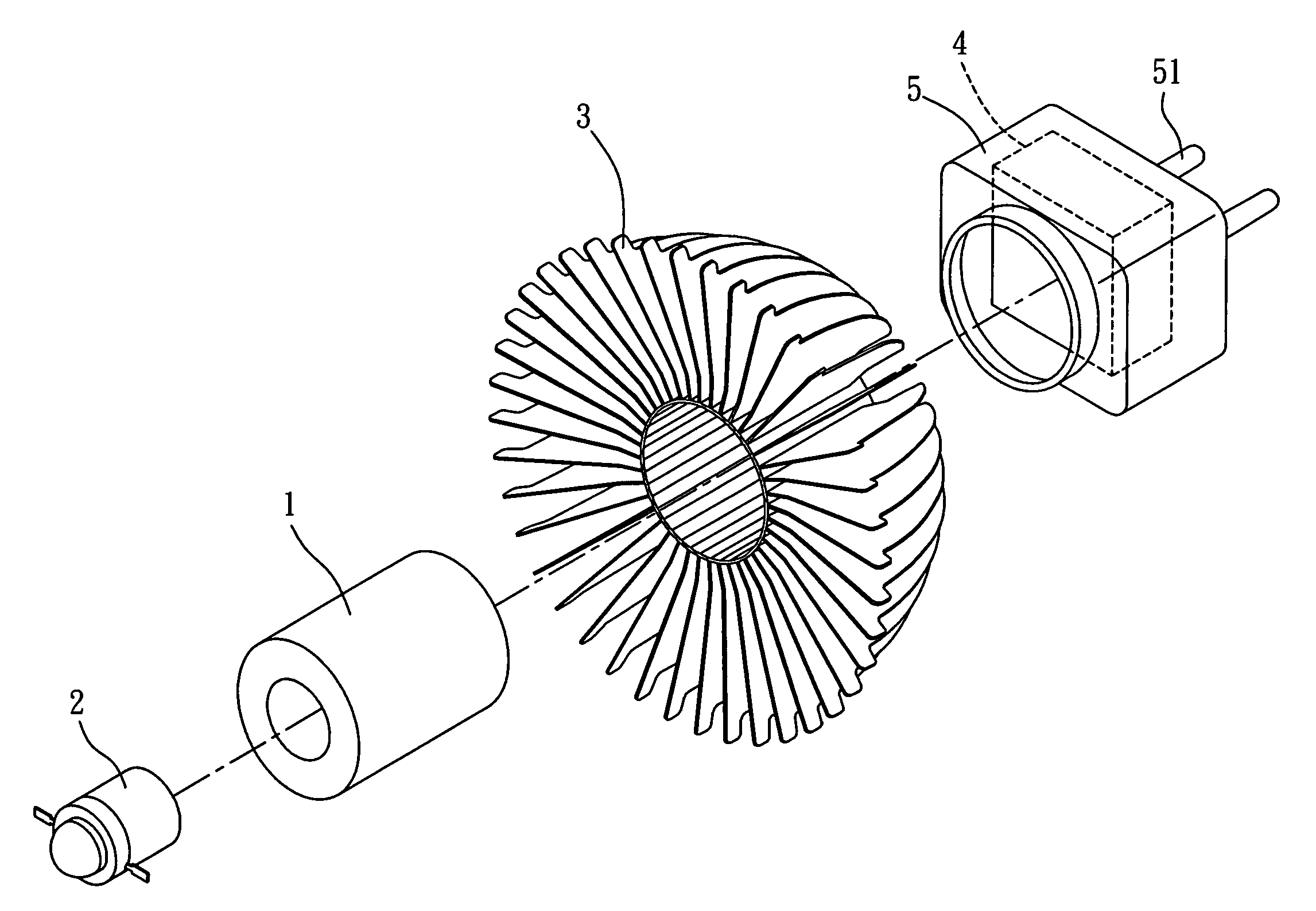
[0019]Referring to FIG. 3 which is an exploded view of the invention, the LED projector light module comprises a main body 1, a LED unit 2, a heat-radiating unit 3, a voltage conversion unit 4, and a base 5. The main body 1 is made of metallic material with good thermal conductivity (e.g. copper) and contains a space 11 for accommodating the LED unit 2. The LED unit 2 and the voltage conversion unit 4 are electrically connected. The voltage conversion unit 4 is configured inside the base 5. The base 5 is connectable to the main body 1. The bottom surface of base 5 is disposed with an electrically conductive pin 51 that matches the projector socket 6 (as shown in FIG. 4). The electrically conductive pin 51 is electrically connected to the voltage conversion unit 4 at one end. The invention is characterized in which the heat-radiating unit 3 is arranged at the outer rim of main body 1 and the heat generated by the LED unit 2 can be effectively transferred to the heat-radiating unit 3 ...


PUM


Abstract

A LED projector light module comprising a main body, a LED unit, a heat-radiating unit, a voltage conversion unit and a base is disclosed. The main body is made of metallic material with good thermal conductivity (e.g. copper) and contains a space for accommodating the LED unit. The LED unit and the voltage conversion unit are electrically connected. The voltage conversion unit is configured inside the base. The base is connectable to the main body. The bottom surface of base is disposed with an electrically conductive pin that matches the projector socket. The electrically conductive pin is electrically connected to the voltage conversion unit at one end. The invention is characterized in which the heat-radiating unit is arranged at the outer rim of main body and the heat generated by the LED unit can be effectively transferred to the heat-radiating unit through the main body and then rapidly dissipate, which enhances the efficiency of heat dissipation, thereby allowing the use of higher wattage LED to enhance luminance.

Description

BACKGROUND OF INVENTION[0001]1. Field of the Invention[0002]The present invention relates to a LED projector light module, more particularly a kind of LED projector light module that can be directly mounted on a conventional MR-16 socket, uses the light emitted by LED to provide the light source, and has heat-radiating fins disposed at the outer rim of LED.[0003]2. Description of the Prior Art[0004]Projector lamps have long accounted for a certain percentage of the lamp market. Particularly as energy-saving light bulbs are gradually replacing conventional fluorescent tubes, projector lamp remains popular due to the special illumination effect it can create. Projector lamps have been used in home furbishing, showrooms and restaurants to foster unique atmosphere and highlight the products or decorations on display. Given its substantial market scale, the dimensions of projector lamps are already standardized. Conventional projector lamps use 110-volt halogen light bulb A (FIG. 1). Hal...

Claims


Application Information

Patent Timeline
Patent Type & Authority Patents(United States)
IPC IPC(8): F21V29/00F21S2/00F21V19/00F21Y101/02H01L33/00H01L33/60
CPCF21K9/137F21V29/89F21V29/83F21V29/773F21Y2101/02F21K9/233F21Y2115/10
Inventor CHIEN, CHEN-CHUN
Owner FIN CORE
Why Eureka
Try Eureka