Antenna device and door handle device

an antenna device and door handle technology, applied in anti-theft devices, wing knobs, instruments, etc., can solve the problems of limited shape of door handles, small space inside the door handle, and inability to accommodate transmission antennas and sensor electrodes, so as to reduce the number of components

Inactive Publication Date: 2010-03-16
AISIN SEIKI KK
View PDF75 Cites 7 Cited by
  • Summary
  • Abstract
  • Description
  • Claims
  • Application Information

AI Technical Summary

Benefits of technology

[0015]The coil and the transceiver drive circuit are connected by the transformer. Thus, the coil and the transceiver drive circuit are connected so that alternating current flows therebetween and direct current does not flow therebetween. The transformer disconnects the capacitance detector and the transmission drive circuit so that direct current does not flow therebetween. Therefore, even if the transmission drive circuit includes a MOSFET having parasitic capacitance and the MOSFET is grounded, the portion of the sensor electrode around which the coil is wound is prevented from becoming the non-detection area regardless of the magnitude of the parasitic capacitance of the MOSFET. Further, the coil and the transmission drive circuit are connected by the transformer so that alternating current flows therebetween. Thus, the electrical signal output from the transmission drive circuit is transmitted from the antenna through the transformer. Therefore, unlike when the coil and the transmission drive circuit are connected by switches. a control circuit for controlling a switch is not necessary. Thus, the antenna device does not have to be enlarged.
[0017]In the present invention, the core is preferably made of amorphous alloy. Amorphous alloy is conductive and has higher permeance and superior high frequency characteristics in comparison with, for example, steel plates or silicon plates. Accordingly, the amorphous alloy core sheet is optimal for use as a highly sensitive sensor electrode and contributes to enhancing the performance and miniaturization of the transceiver antenna.
[0019]In the present invention, at least part of the coil is easily used as the sensor electrode. This reduces the number of components accommodated in the handle.

Problems solved by technology

The door handle does not accommodate only the transmission antenna and the sensor electrode, and the space inside the door handle is not large.
Otherwise, limitations are applied to the shape of the door handle in accordance with the shapes of the components accommodated in the door handle.
However, it is difficult to connect the conductive wire, which extends from the capacitance detector, to the core.
However, such a waterproof structure would increase the manufacturing cost.

Method used


Image

  • Antenna device and door handle device
  • Antenna device and door handle device
  • Antenna device and door handle device

Examples


first embodiment

[0027]A first embodiment of the present invention will now be described with reference to the drawings.

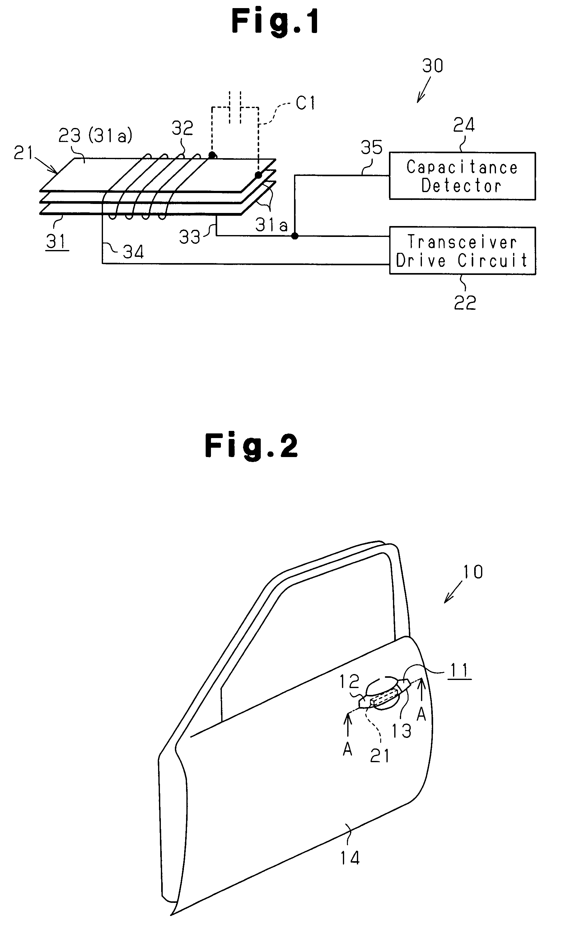
[0028]As shown in FIG. 2, an outside handle 11 is arranged on a vehicle door 10. The outside handle 11 is attached to a door outer panel 14 of the vehicle door 10 at the rear side of the vehicle door 10.

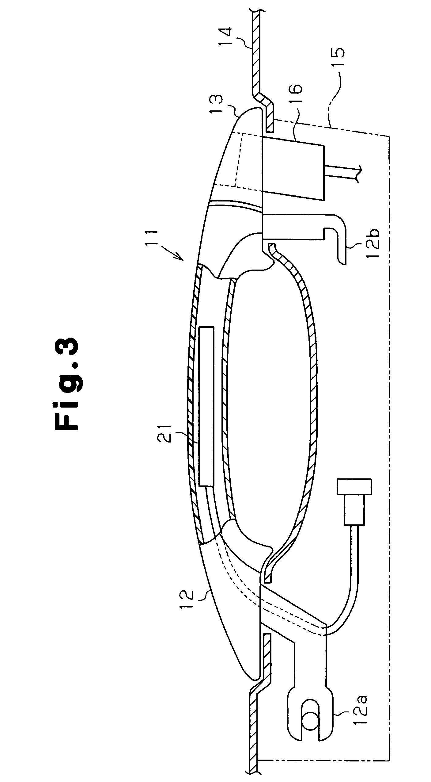
[0029]As shown in FIG. 3, the outside handle 11 includes a handle portion (grip) 12, a handle cap 13 projecting out of the vehicle from the door outer panel 14, and a handle frame 15 fixed to the door outer panel 14 inside the vehicle door 10. A user (e.g., owner, driver, passenger of the vehicle) grips and pivots the handle portion 12 when opening and closing the vehicle door 10. The handle portion 12 is connected to the handle frame 15 in a manner that it is pivotal in a predetermined range and so that the door outer panel 14 is arranged between the handle portion 12 and the handle frame 15. More specifically, a hinge arm 12a and a stroke arm 12b are respectively arranged at the t...

second embodiment

[0049]A second embodiment of the present invention will now be described with reference to the drawings. Like or same reference numerals are given to those components that are the same as the corresponding components of the first embodiment, and such components will not be described in detail.

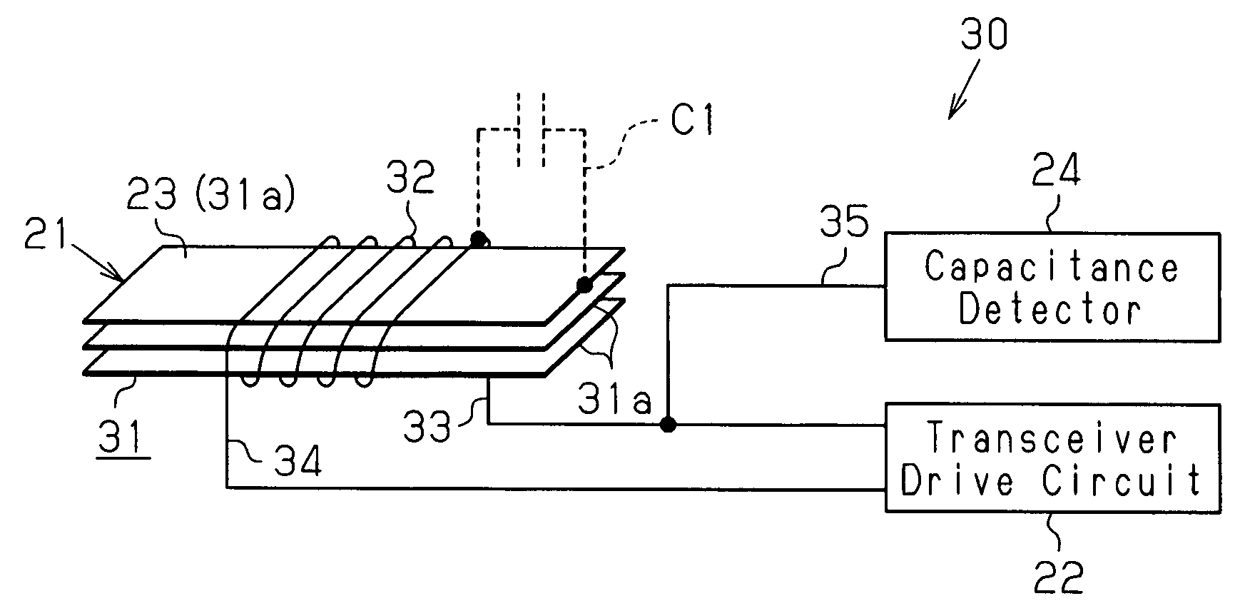
[0050]FIG. 5 shows an antenna device 40 of the second embodiment. As shown in FIG. 5, the coil 32 and the transceiver drive circuit 22 are connected by switches 41 and 42. The conductive wire 35, which extends from the capacitance detector 24, is connected to a conductive wire 33a, which extends between the switch 41 and the coil 32, so that a connection point 35a is located on the conductive wire 33a. This electrically connects a capacitance detector 24 to the coil 32.

[0051]The switch 41 includes a movable terminal 41a connected to the conductive wire 33a extending from one end of the coil 32 and a contact point 41b connected to a conductive wire 33b extending from the transceiver drive circui...

third embodiment

[0061]A third embodiment of the present invention will now be described with reference to the drawings. Like or same reference numerals are given to those components that are the same as the corresponding components of the first and second embodiments, and such components will not be described in detail.

[0062]FIG. 7 shows an antenna device 60 of the third embodiment. The antenna device 60 of the third embodiment includes the transmission drive circuit 50 in the same manner as in the transceiver drive circuit 22 of the second embodiment. As shown in FIG. 7, the coil 32 and the transceiver drive circuit 22 are connected by a transformer 61. The transformer 61 connects the coil 32 and the transceiver drive circuit 22 so that alternating current flows therebetween and direct current does not flow therebetween. The conductive wire 35, which extends from the capacitance detector 24, is connected to the conductive wire 33a so that the connection point 35a is located on the conductive wire ...


PUM


Abstract

A transmission / reception antenna (21) comprises a core (31) and a coil (32) wound around the core (31). One of a plurality of core sheets (31a) constituting the core (31) is utilized as a sensor electrode (23). Conductors (33, 34) extending from the two ends of the coil (32) are connected to a transmission / reception drive circuit (22). The conductor (35) extending from a capacitance detector (24) is connected to one of the conductors (33, 34) extending between the coil (32) and the transmission / reception drive circuit (22). Consequently, the capacitance detector (24) is alternately connected to the sensor electrode (23) through a parasitic capacitance C1 generated between the coil (32) and the sensor electrode (23) (core sheet (31a)).

Description

FIELD OF THE INVENTION[0001]The present invention relates to an antenna device for use in an electronic key system for recognizing the intention of a user to lock or unlock a vehicle door and controlling the locking and unlocking of the vehicle door, and a door handle device including the antenna device.BACKGROUND OF THE INVENTION[0002]Patent publication 1 discloses a vehicle door handle used in an electronic key system for locking and unlocking a vehicle door in response to a portable device carried by a user. The vehicle door handle disclosed in patent document 1 accommodates a transmission antenna for communicating with the portable device and a sensor electrode for detecting the user approaching the vehicle door based on a change in capacitance. The transmission antenna includes a core and a coil, which is formed by winding conductive wire around the core. The coil is connected to a transmission drive circuit, which transmits a transmission request signal from the transmission a...

Claims


Application Information

Patent Timeline
Patent Type & Authority Patents(United States)
IPC IPC(8): H01Q1/32B60J5/04B60R25/01B60R25/24E05B1/00E05B81/78E05B85/16G01B7/00H01Q7/08
CPCB60R25/246E05B81/78H01Q1/3283H01Q1/44H01Q7/08E05B81/77G07C9/00309G07C2209/65
Inventor INABA, HISASHIIEDA, KIYOKAZUHATANO, RIKUO
Owner AISIN SEIKI KK
Why Eureka
Try Eureka