Lens driving device, optical pick up device and adjusting method

a technology of optical pick-up device and driving device, which is applied in the manufacture of optical heads, instruments, data recording, etc., can solve the problems of reducing the bearing length of the holder, affecting the playability of the optical pick-up system, and reducing the span of the holder guide shaft or its length, so as to reduce the straightness error prolong the focal length of the collimation lens. , the effect of reducing the straightness error

Inactive Publication Date: 2010-03-16
MITSUBISHI ELECTRIC CORP
View PDF28 Cites 0 Cited by
  • Summary
  • Abstract
  • Description
  • Claims
  • Application Information

AI Technical Summary

Benefits of technology

[0006]Consequently, in order to reduce the straightness error of a collimation lens in conventional optical pick up devices, countermeasures such as making longer the focal length of the collimation lens, making longer the bearing length of a holder supporting the collimation lens, and making longer a span between the guide shafts in the holder and a holder length across which the guide shafts hold the holder, whereby accuracy in straightness of the lens has been mechanically secured. Meanwhile, these countermeasures have caused the structures for holding and supporting the collimation lens to become bulky accordingly. On the other hand, if countermeasures are simply taken to cope with a request for downsizing the device, the span of the holder guide shafts or their length is shortened or the focal length of the collimation lens is made shorter, which arises a problem in that offsets of sensor signals increase.

Problems solved by technology

If the straightness error of the collimation lens is large in the optical pick up device whose focusing system uses a method, as described above, of moving the collimation lens, the collimation lens movement may cause movements of a light beam spot on an optical sensor of an optical sensing system, which results in offsets of sensor signals, affecting playability of the optical pick up system.
Meanwhile, these countermeasures have caused the structures for holding and supporting the collimation lens to become bulky accordingly.
On the other hand, if countermeasures are simply taken to cope with a request for downsizing the device, the span of the holder guide shafts or their length is shortened or the focal length of the collimation lens is made shorter, which arises a problem in that offsets of sensor signals increase.

Method used


Image

  • Lens driving device, optical pick up device and adjusting method
  • Lens driving device, optical pick up device and adjusting method
  • Lens driving device, optical pick up device and adjusting method

Examples


embodiment 1

[0068]A lens driving device and an optical pick up device of Embodiment 1 according to the present invention will be explained below, using figures. The lens driving device according to Embodiment 1 has a feature in its structure with which its mounting angles can be adjusted with respect to the optical pick up device.

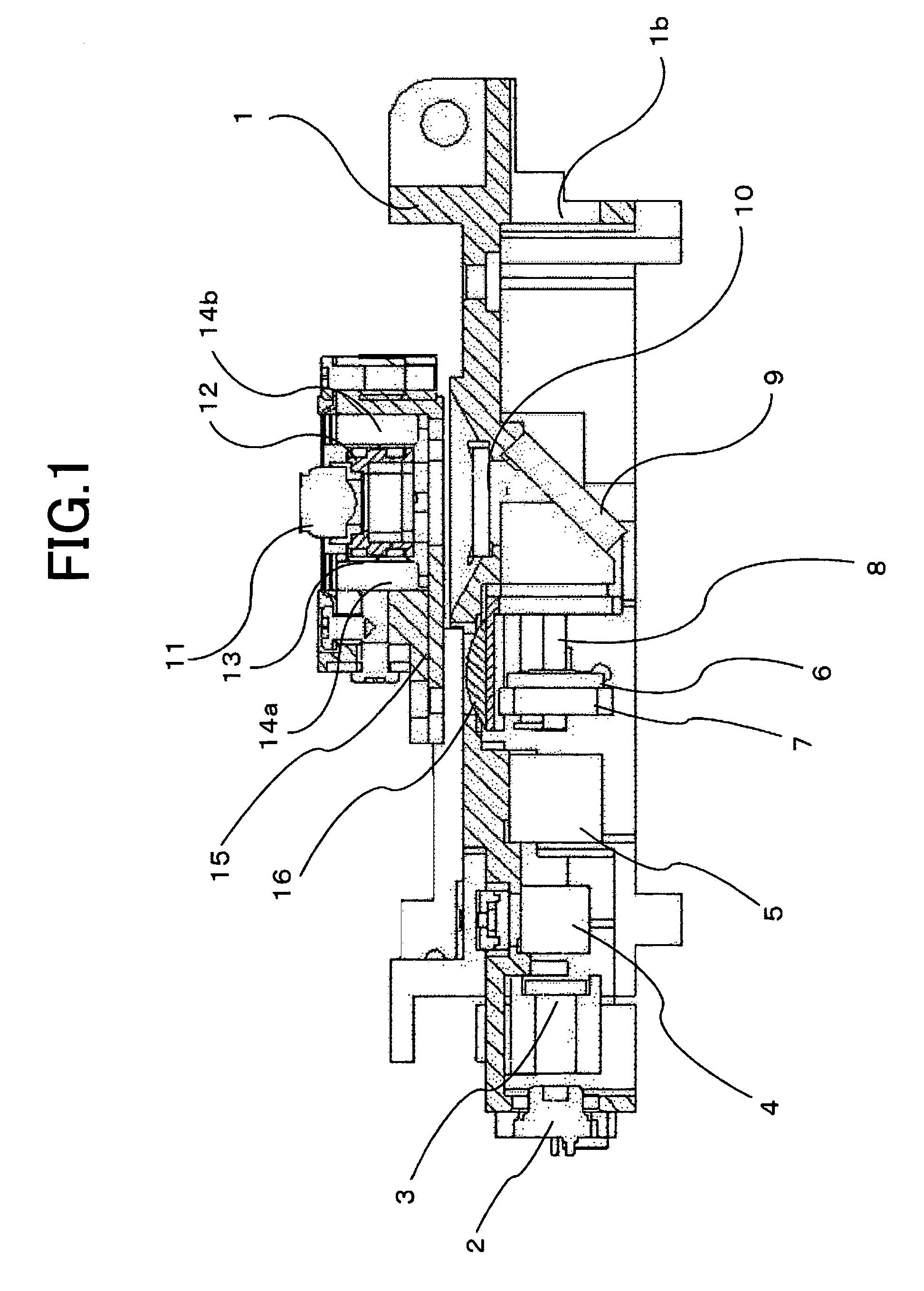
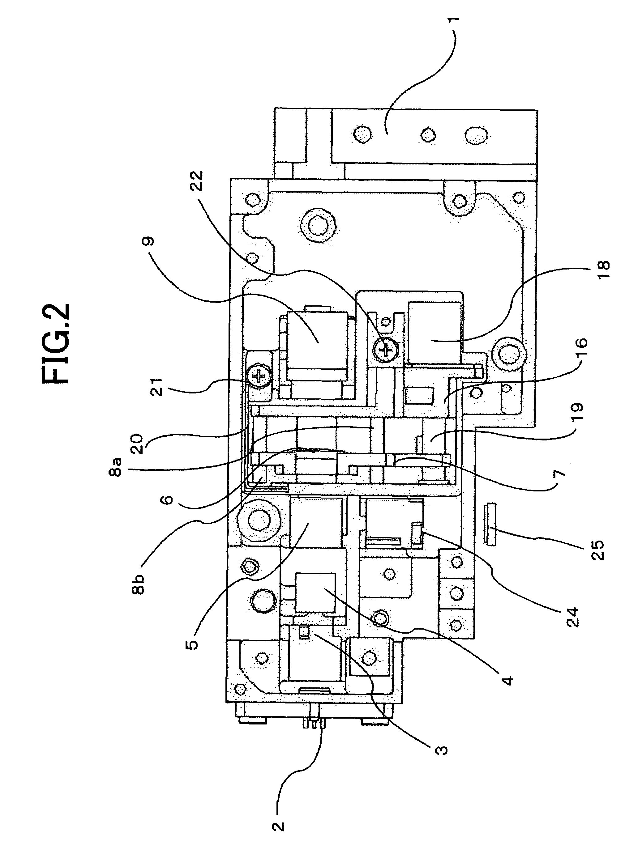
[0069]FIG. 1 is a cross-sectional view of the optical pick up device on which the lens driving device of Embodiment 1 according to the present invention is mounted.

[0070]The lens driving device includes a function to correct spherical aberration caused by differences among transparent layers, which will be described later. Each component of the optical pick up device will be explained, using FIG. 1.

[0071]A base 1 is provided with a semiconductor laser 2, a diffraction grating 3, a dichroic prism 4, and a polarizing prism 5. The semiconductor laser 2 emits light as a divergent light beam, which reaches a collimation lens 6 to be converted into a collimated light beam. T...

embodiment 2

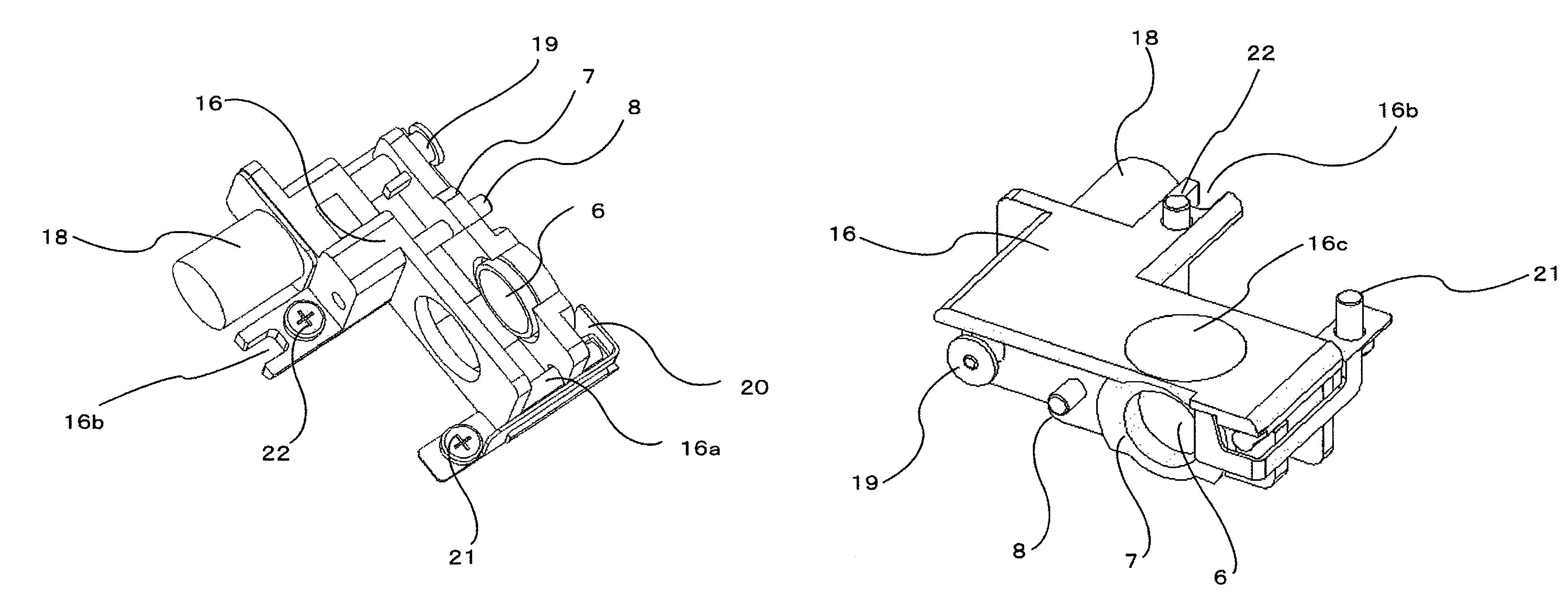
[0110]FIG. 11 is a perspective view for explaining a lens driving device according to Embodiment 2, which view corresponds to that for Embodiment 1 shown in FIG. 4. As obviously shown in the figure, the lens driving device according to the present embodiment has a feature in that a cylindrical protrusion 500 is integrally formed with a mounting base 16.

[0111]A base 1 of an optical pick up device has a spherical concave portion that opposes to the protrusion 500. The spherical center of the spherical concave portion is positioned on the central optical axis of the collimation lens.

[0112]Then, the cylindrical protrusion 500 is fitted onto the concave portion, which is configured in a spherical shape on the base 1, to be fixed with a spring 20 and screws 21 and 22. Since detail adjustment procedures hereinafter are the same as those in Embodiment 1, explanations will be omitted.

[0113]As described above, adjustment can also be made similarly to that in Embodiment 1, by fitting a cylindr...


PUM

PropertyMeasurementUnit
wavelengthaaaaaaaaaa
thicknessaaaaaaaaaa

Abstract

A lens driving device according to the present invention includes a mounting base; a collimation lens that is engaged with the mounting base and movable in optical axis directions; and a driving source that moves the collimation lens in the optical axis directions, and the mounting base includes a fulcrum section with which, when the driving device is mounted on a base, a pitch angle and a roll angle of the driving device are adjusted with respect to the base and the optical axis.

Description

TECHNICAL FIELD[0001]The present invention relates to lens driving devices used in optical pick up devices that record and reproduce information on / from optical media such as optical disks and relates to those optical pick up devices. It also relates to mounting and adjusting methods when the lens driving devices are mounted on the optical pick up devices.BACKGROUND OF THE INVENTION[0002]Typically, a transparent layer is provided on the data recording face of an optical medium to protect the face. In order to correct spherical aberration caused by differences in thickness among transparent layers, a correction method may be sometimes used in a conventional optical pick up device in which a lens driving means moves a collimation lens to correct a convergence-divergence angle of a light beam entering an objective lens. Another correction method may also be used in which a lens driving means moves a beam expanding lens to correct a convergence-divergence angle of a light beam entering ...

Claims


Application Information

Patent Timeline
Patent Type & Authority Patents(United States)
IPC IPC(8): G02B7/02G11B7/00
CPCG11B7/082G11B7/1376G11B7/13925G11B7/22
Inventor MATOZAKI, TOSHIYATAKESHITA, NOBUO
Owner MITSUBISHI ELECTRIC CORP
Why Eureka
Try Eureka