Specific absorption rate measurement system and method

a measurement system and absorption rate technology, applied in the field of measurement systems, can solve the problems of increasing measurement time, difficult to enable a highly accurate estimation of the 3-dimensional sar distribution, complicated scanning method and/or arrangement of the sensor apparatus, etc., and achieves the reduction of the period of time, simplified sar estimation procedures and the measurement system, and highly accurate 3-dimensional sar distribution.

Inactive Publication Date: 2010-03-23
NTT DOCOMO INC
View PDF8 Cites 9 Cited by
  • Summary
  • Abstract
  • Description
  • Claims
  • Application Information

AI Technical Summary

Benefits of technology

[0017]According to another embodiment of the present invention, the SAR estimation procedures and the measurement system can be simplified, and a highly accurate 3-dimensional SAR distribution can be calculated in a reduced period of time.

Problems solved by technology

Therefore, it is difficult to enable a highly accurate estimation of the 3-dimensional SAR distribution, especially under situations where the SAR distribution in the medium depends strongly on types of mobile phones or the like.
The unnecessarily large number of measurement points makes a scanning method and / or arrangement of a sensor apparatus complicated, and requires additional calculations of the magnetic or electric field, which may lead to a problem of increased measurement time.

Method used


Image

  • Specific absorption rate measurement system and method
  • Specific absorption rate measurement system and method
  • Specific absorption rate measurement system and method

Examples


example 1

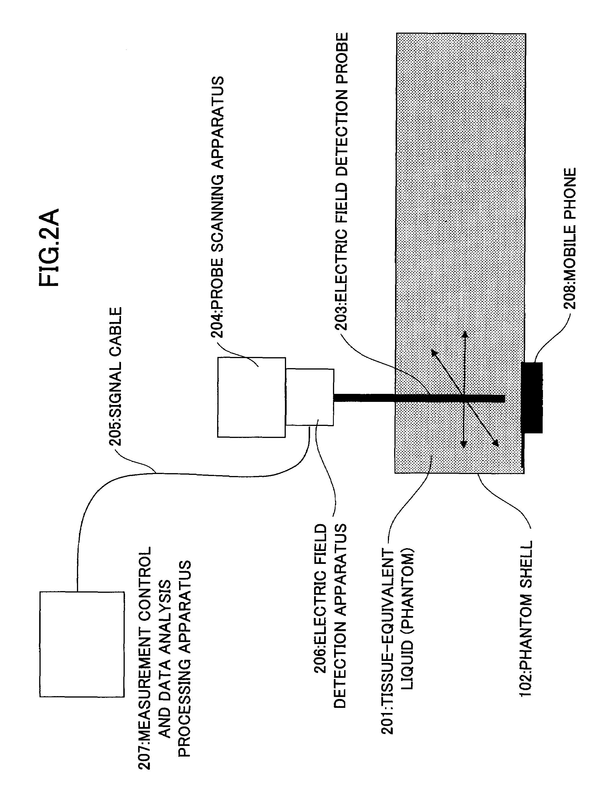
[0051]FIG. 2A is a schematic view of a fast SAR measurement system according to a first example of the present invention. As shown, the fast SAR measurement system includes tissue-equivalent liquid (phantom) 201 having predetermined dielectric constants so as to simulate a human body, a phantom shell 202, an electric probe 203, a probe scanning apparatus 204, a signal cable 205, an electric field detection apparatus 206, and a measurement control and data analysis processing apparatus 207. In this system, a radio terminal apparatus such as a mobile phone 208 or the like is attached on the phantom shell 202 as shown FIG. 2A, and the electric field generated in the phantom 201 is measured. The radio terminal apparatus may be, for example but not limited to, a personal digital assistance (PDA), a desk top computer, a hand-held computer, a credit card identification terminal, a camera, and a wearable computer, all of which have a radio communications function or a network connectable fu...

example 2

[0066]In the above Example 1, one electric field sensor (probe or the like) is used to measure the 2-dimensional electric field distribution. However, plural sensors may be arranged in array to measure the electric field distribution. When an array sensor is used, scanning time of the electric field sensor can be largely reduced, thereby enabling higher speed measurement of SAR. However, when plural sensors are concurrently used, it may become inconvenient to scan all the plural sensors according to circumstances. In this case, it is advantageous to make the mobile phone scannable.

[0067]FIG. 7 shows a fast SAR measurement system according to a second example of the present invention. In the second example, plural probes 703 arranged in array are used for the measurement. As shown, plural probes are arranged at predetermined intervals in a measurement area in which the measurement on the 2-dimensional observation surface S is to be performed. The predetermined intervals may be 8.0 mm...

example 3

[0069]FIG. 8 is a functional block diagram of a fast SAR measurement process according to a third example of the present invention. In this example, a measured electric field information determination apparatus 806 controls an electric field distribution measurement system 801 so that both amplitude and phase are measured for the electric field components parallel to the observation surface S and only amplitude is measured for the electric field component perpendicular to the observation surface S.

[0070]FIG. 9 shows electric field coordinates in relation to the observation surface S. In this figure, the observation surface S is formed as the xy-plane.

[0071]Therefore, both amplitude and phase (Exejθx, Eyejθy) of the electric field components Ex, Ey parallel to the observation surface S are measured and only the amplitude of the electric field component Ez perpendicular to the observation surface S is measured. The electric field components in the dielectric medium away from the obser...


PUM


Abstract

A disclosed specific absorption rate measurement system according to an embodiment of the present invention measures a specific absorption rate of electromagnetic waves from a radiating source absorbed in a dielectric medium. The system includes a measurement portion that measures a first electric field vector on an observation surface which is a two-dimensional surface in the dielectric medium; an electric field calculation portion that calculates a second electric field vector in a point excluded from the observation surface in accordance with electric field components of the first electric field vector measured on the observation surface, the electric field components being parallel to the observation surface; and a calculation portion that calculates the specific absorption rate from the calculated second electric field vector.

Description

BACKGROUND OF THE INVENTION[0001]1. Field of the Invention[0002]The present invention relates to a measurement system and a method which measure a Specific Absorption Rate (SAR) at which electromagnetic energy from a radiating source, such as a mobile phone or the like, is absorbed in a dielectric medium during exposure.[0003]2. Description of the Related Art[0004]A Specific Absorption Rate (SAR) is a rate at which electromagnetic energy from a radiating source is absorbed in a dielectric medium and specifically defined as a value proportional to the second power of electric field strength (|E|2) as expressed by the numeric equation (1).[0005]SAR=σ⁢E2ρ(1)where σ represents the electric conductivity (S / m) of a dielectric medium, and ρ is the density (kg / m3) of the medium. The unit of measurement of SAR is W / kg. The SAR is specifically used to evaluate electric energy absorbed in a human body when a mobile phone or the like is used near the human body (see non-patent document 1).[0006...

Claims


Application Information

Patent Timeline
Patent Type & Authority Patents(United States)
IPC IPC(8): G01R27/04
CPCG01R29/0857G01R29/0885G01R29/0871G01R29/08
Inventor KIMINAMI, KATSUKIIYAMA, TAKAHIROONISHI, TERUO
Owner NTT DOCOMO INC
Why Eureka
Try Eureka