Camera using multiple lenses and image sensors in a rangefinder configuration to provide a range map

a range map and image sensor technology, applied in the field of digital cameras, can solve the problems of inability to accurately determine the focus setting of the “through-the-lens” autofocus system, inability to maintain the dual-lens rangefinder module and the adjustable focus lens position in the normal operating environment of digital cameras, and inability to accurately determine the focus setting. the effect of rapid autofocus, precise and accurate measuremen

Active Publication Date: 2010-03-23
MONUMENT PEAK VENTURES LLC
View PDF16 Cites 45 Cited by
  • Summary
  • Abstract
  • Description
  • Claims
  • Application Information

AI Technical Summary

Benefits of technology

[0036]In thus utilizing the invention, a digital camera advantageously provides precise, rapid autofocus in both still and video modes without unduly increasing the size or cost of the digital camera. Moreover, a further advantage is that the two capture stages can be used together in a rangefinder mode to produce a range map, and the camera can be configured to determine GPS locations for portions of the scene in the range map. Given the GPS locations, identities of objects in the scene can be identified and catalogued.

Problems solved by technology

For example, sonic autofocus systems cannot focus through a glass window as the glass stops the projected sonic signal, thereby causing the autofocus system to focus onto the glass.
The problem with dual lens rangefinder modules is that the calibration between the dual lens rangefinder module and the adjustable focus lens position is not stable within the normal operating environment for digital cameras.
In addition, the measured position of the adjustable focus taking lens in the adjustable focus taking lens system is prone to environmentally induced changes as well so that inaccuracies are produced in the control system for the adjustable focus lens.
Unfortunately, “through-the-lens” autofocus systems can be relatively slow in determining a focus setting due to the large number of autofocus images that must be captured and compared.
This is a particular problem in video focusing, where a new subject at some distance away from the present subject may come into the image and never be detected by the “hill climb” method—even where the new subject may present a greater “hill” in terms of contrast values.
However, in both this patent application and product, only one of the two image sensors is used at a time.
A problem with these prior art systems is that either a separate autofocus sensor must be used (thus increasing the cost) or else there is typically a significant “shutter delay” as the autofocus is performed using the same sensor that is used to capture the image.
Moreover, the separate autofocus sensor is usually a rangefinder and, as mentioned above, the calibration between the dual lens rangefinder module and the adjustable focus lens position is not stable within the normal operating environment for digital cameras.
Where the autofocus is performed with the “through-the-lens” taking system, the process can be relatively slow in determining a focus setting due to the large number of autofocus images that must be captured and compared.
US 2003 / 0160886, but difficulties remain in rapidly achieving focus as the subject changes or moves, or in rapidly interchanging the focusing requirements of the optical systems when the operator elects to change the capture function from one photographing system to the other.
A special problem arises during video capture, where the autofocus images are derived from the same series of still images or frames that compose the video images.
As a result, during video capture with pan movements of the camera where the scene changes continuously, large portions of the video are actually out of focus as the autofocus system hunts for proper focus.
A further problem is that during video capture, many of the frames are out of focus due to the use of an autofocus system that uses the “hill climb method” to focus.

Method used


Image

  • Camera using multiple lenses and image sensors in a rangefinder configuration to provide a range map
  • Camera using multiple lenses and image sensors in a rangefinder configuration to provide a range map
  • Camera using multiple lenses and image sensors in a rangefinder configuration to provide a range map

Examples


Embodiment Construction

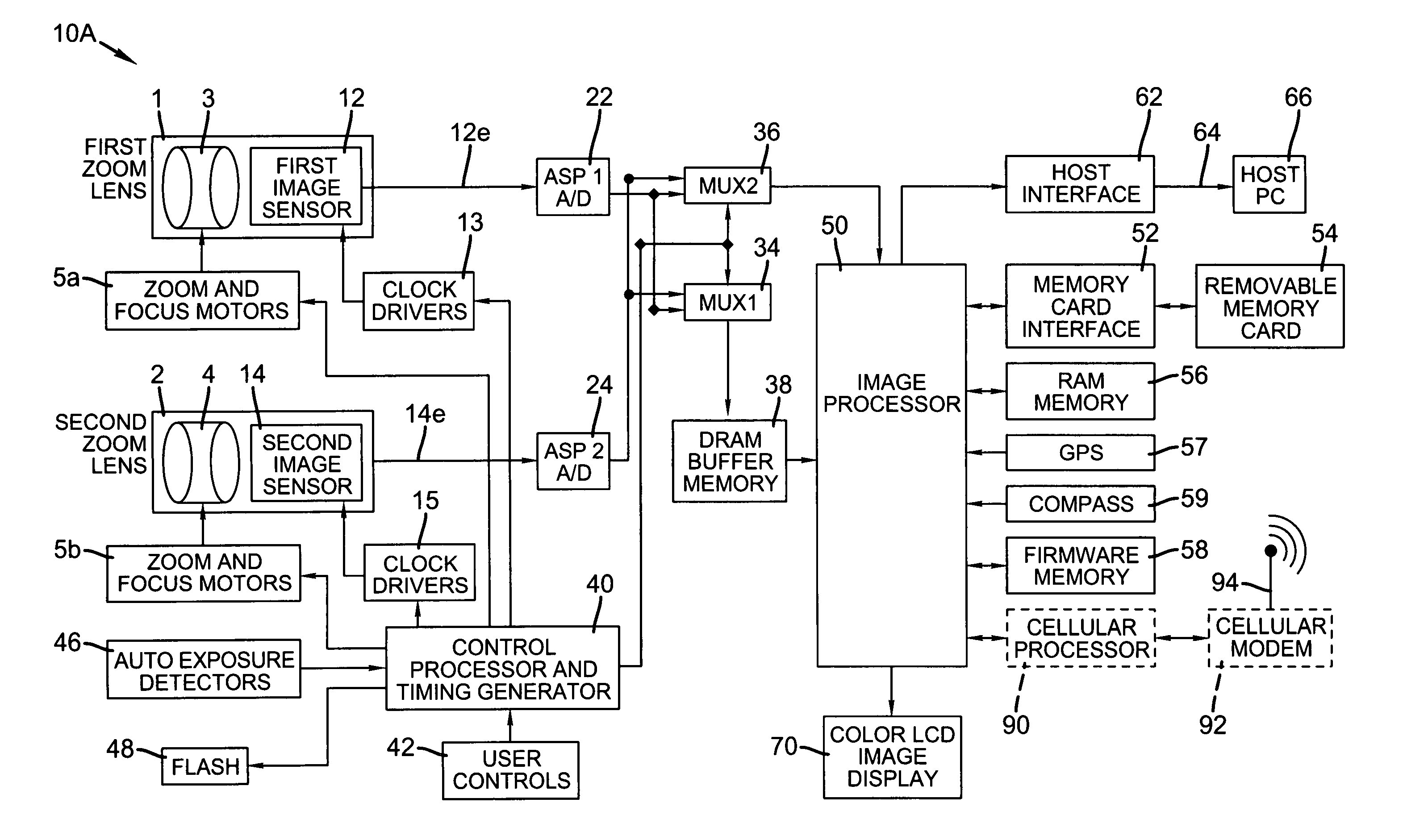
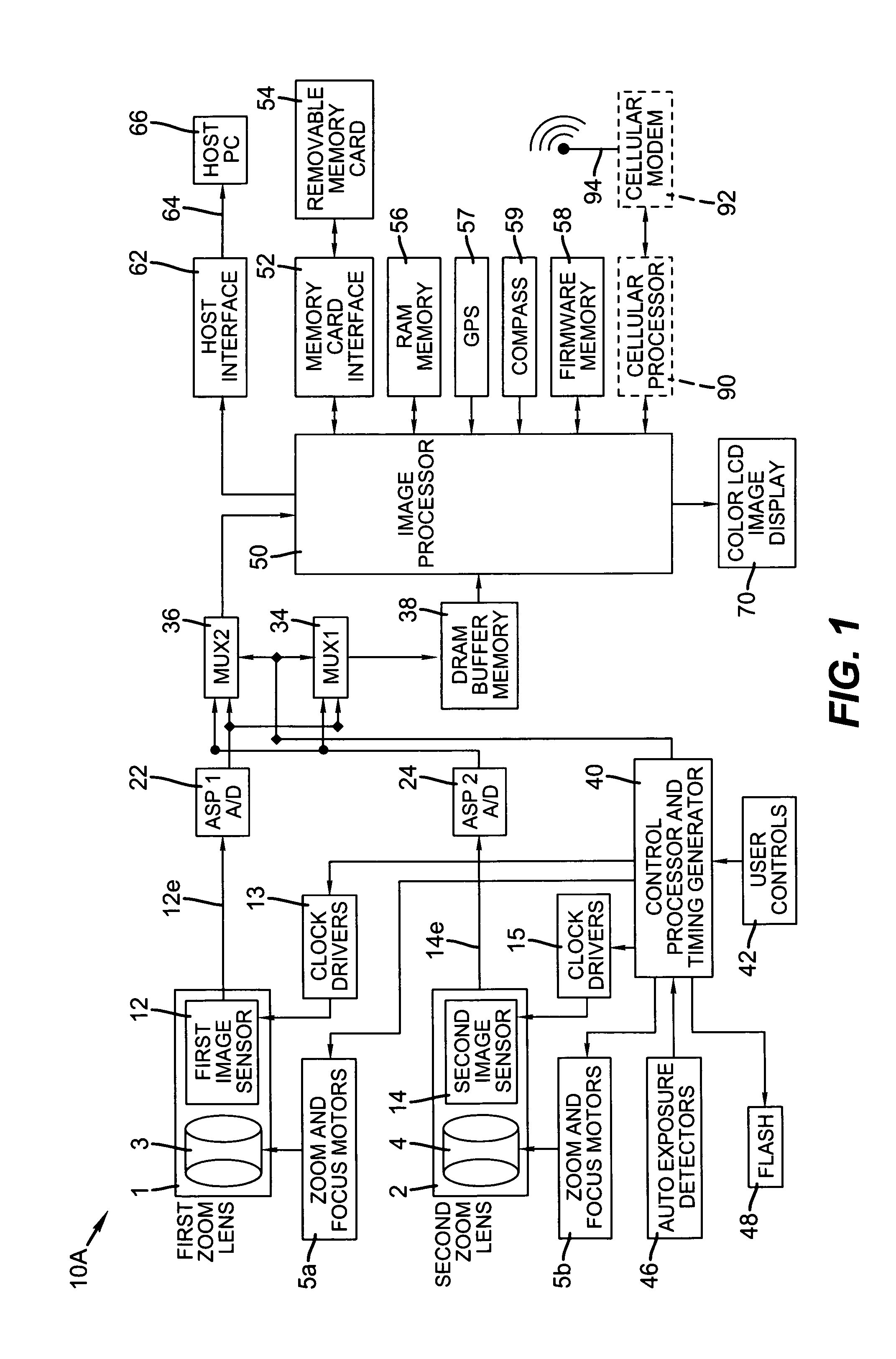
[0067]Because digital cameras employing imaging devices and related circuitry for signal processing are well known, the present description will be directed in particular to elements forming part of, or cooperating more directly with, apparatus in accordance with the present invention. Elements not specifically shown or described herein may be selected from those known in the art. Certain aspects of the embodiments to be described may be provided in software. Given the system as shown and described according to the invention in the following materials, software not specifically shown, described or suggested herein that is useful for implementation of the invention is conventional and within the ordinary skill in such arts.

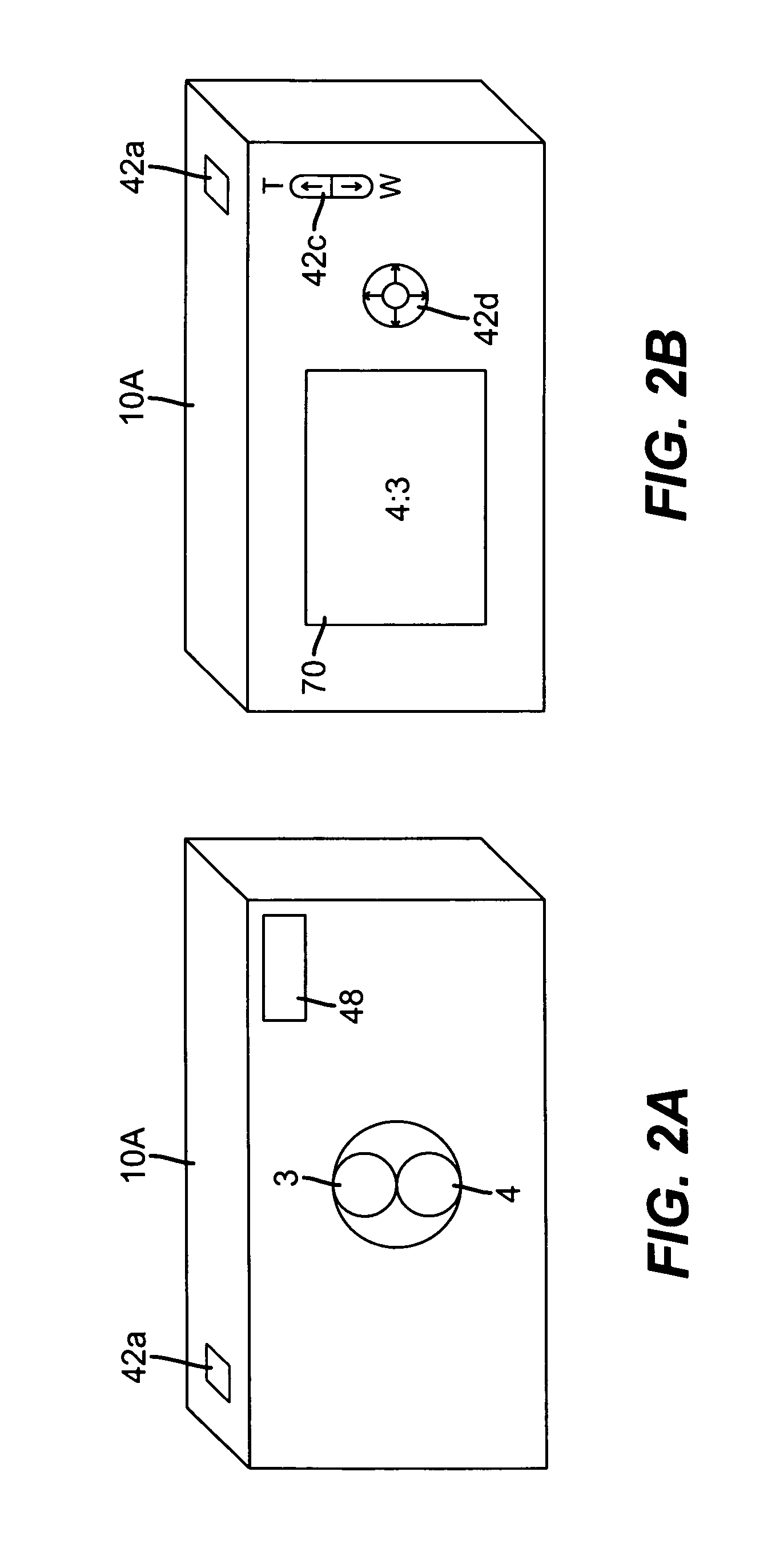
[0068]Each of the several embodiments described herein include an image capture assembly, such as a digital camera—still or video—or a digital scanner, having multiple image capture stages, each composed of a lens and an image sensor, wherein the lenses of the mult...


PUM


Abstract

An electronic camera for producing an output image of a scene from a captured image signal includes a first imaging stage comprising a first image sensor for generating a first sensor output and a first lens for forming a first image of the scene on the first image sensor, and a second imaging stage comprising a second image sensor for generating a second sensor output and a second lens for forming a second image of the scene on the second image sensor, where the lenses have different focal lengths. A processing stage uses the sensor output from one of the imaging stages as the captured image signal and uses the images from both imaging stages to generate a range map identifying distances to the different portions of the scene.

Description

FIELD OF THE INVENTION[0001]The present invention relates to a digital camera that produces digital image files and, more particularly, to a digital camera that uses multiple lenses and image sensors to provide improved rangefinding capability.BACKGROUND OF THE INVENTION[0002]Currently, most digital cameras use a zoom taking lens and a single color image sensor to capture still and motion images. The captured images are then processed to produce digital image files, which are stored in a digital memory in the camera. The digital image files can then be transferred to a computer, displayed, printed, and shared via the Internet.[0003]In order to capture sharp images of moving subjects, a digital camera needs to provide a precise automatic lens focusing system (i.e., an autofocus system). The autofocus system must be capable of quickly obtaining the correct focus in order to minimize the “shutter delay” between the time the shutter button is pressed and the still image is captured. The...

Claims


Application Information

Patent Timeline
Patent Type & Authority Patents(United States)
IPC IPC(8): H04N5/232G03B13/00G03B13/34G01S19/51G01S5/14G01S19/45H04N13/239
CPCG01S19/45G03B13/36G03B15/00G03B29/00H04N5/2226H04N5/2258H04N5/232H04N5/23212H04N5/23296H04N13/0239H04N13/025H04N13/239H04N13/25H04N23/45H04N23/673H04N23/631H04N23/69
Inventor BORDER, JOHN N.ENGE, AMY D.MORALES, EFRAIN O.PILLMAN, BRUCE H.JACOBY, KEITH A.ADAMS, JR., JAMES E.PALUM, RUSSELL J.GALLAGHER, ANDREW C.
Owner MONUMENT PEAK VENTURES LLC
Why Eureka
Try Eureka