
MIMO multiple transmission device and method

a transmission device and multiple transmission technology, applied in the field of multiple transmission devices and methods, can solve the problems of increasing data rate, increasing data error rate, etc., and achieving the effect of small wastefulness in resending packet data blocks and small channel decoding work load in the receiver sid

Inactive Publication Date: 2010-03-23
NTT DOCOMO INC
View PDF21 Cites 8 Cited by
  • Summary
  • Abstract
  • Description
  • Claims
  • Application Information

AI Technical Summary

Benefits of technology

The solution enables efficient AMC and hybrid ARQ operations, minimizing packet wastefulness and reducing channel decoding workloads on the receiver side, while allowing for adaptive control of channel coding rates and diversity effects across multiple streams.

Problems solved by technology

In general, the more the communication data rate is increased, the more the reception errors occur.
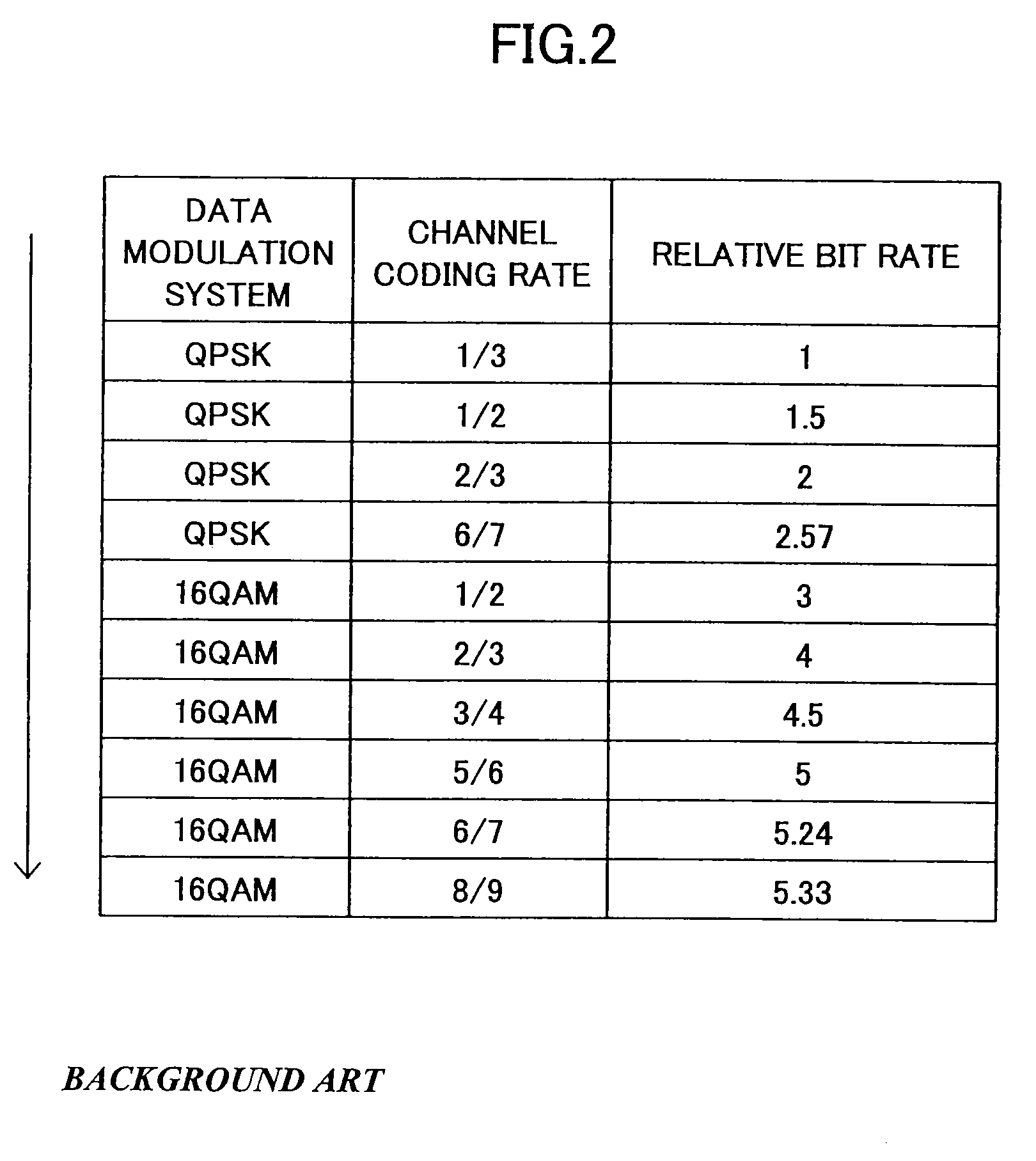
For example, if the data modulation system is changed from 2 bits / 1 symbol QPSK (Quadrature Phase Shift Keying) to 4 bits / 1 symbol 16QAM (Quadrature Amplitude Modulation) or 6 bits / 1 symbol 64QAM, the data rate is increased, but the data error rate is also increased.
In the direction (downward direction) shown by an arrow, the data rates are increased, but the data error rates are also increased.
With regards of this point, the first conventional example shown in FIG. 8 and the third conventional example shown in FIG. 10 are satisfactory, but the second conventional example shown in FIG. 9 does not allow the channel coding rate change to be separately controlled per transmission stream.
The larger the packet data block size becomes, the larger the wastefulness in resending a packet in response to reception error becomes with respect to this point, the second conventional example shown in FIG. 9 and the third conventional example shown in FIG. 10 are disadvantageous.
Further, when the channel coding speed is fast, the work load in the receiver side becomes heavy.

Method used


Image

  • MIMO multiple transmission device and method
  • MIMO multiple transmission device and method
  • MIMO multiple transmission device and method

Examples


Embodiment Construction

[0050]The following is a description of embodiments of the present invention, with reference to the accompanying drawings.

[0051]Throughout all the figures, members and parts having the same or similar functions are assigned the same or similar reference signs, and redundant explanations are omitted.

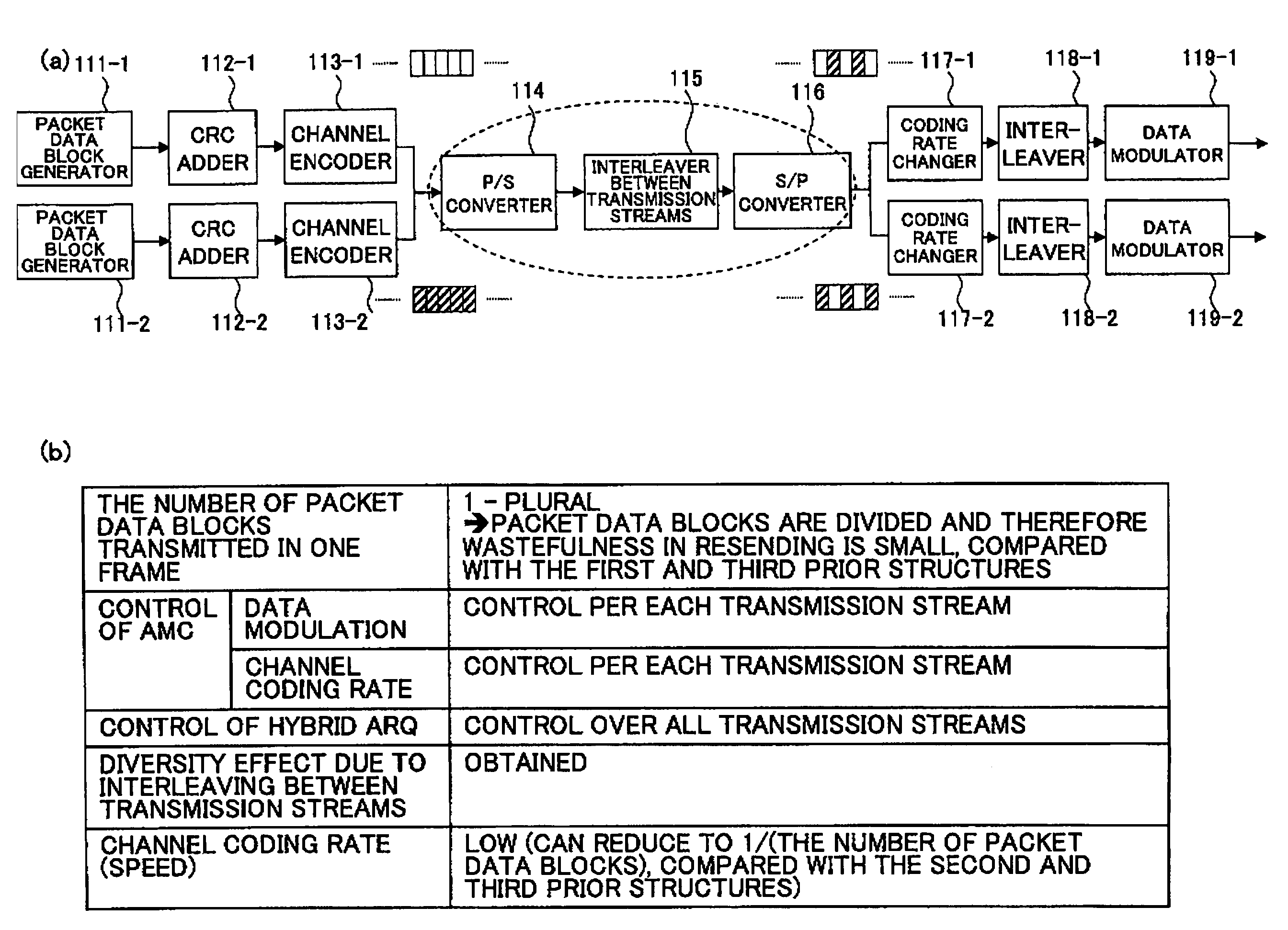
[0052]FIG. 11 is a transmission frame generating unit according to a first embodiment of the present invention. As shown in (a), two upper streams of the transmission frame generating unit comprise packet data block generators 111-1, 111-2 for generating a packet data block as a resending unit in the hybrid ARQ, CRC adders 112-1, 112-2 for adding error detection code, channel encoders 113-1, 113-2 for performing channel encoding in series, respectively. The number of streams may alternatively be one or any number more than two.

[0053]The transmission frame generating unit further comprises a parallel-to serial converter 114 for converting the outputs from the channel encoders 113-1, 113-2 ...


PUM


Abstract

A MIMO multiple transmission device, comprising a packet data block generator (111) for generating a packet data block as a resent unit for hybrid ARQ; a CRC adder (112) for adding an error detection code; a channel encoder (113) for performing channel encoding, the packet data block generator, the CRC adder and the channel encoder being coupled in series in one or more data streams; a parallel-to-serial converter (114) for converting output of the channel encoder to serial form; an interleaver between transmission streams (115) for performing interleaving between transmission streams on outputs from the parallel-to-serial converter; a serial-to-parallel converter (116) for converting outputs from the interleaver between transmission streams to parallel form; a coding rate changer (117) for changing a coding rate; and a data modulator (119) for modulating data, the coding rate changer and the data modulator being connected in series in plural data streams divided by the serial-to-parallel converter.

Description

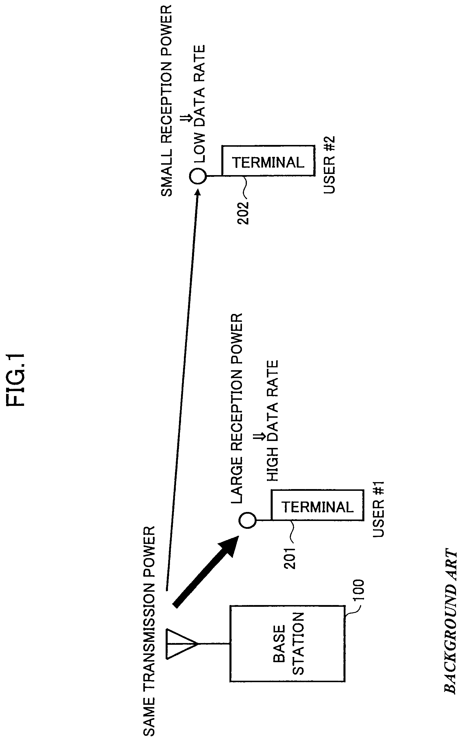
BACKGROUND OF THE INVENTION[0001]The present invention generally relates to a MIMO multiple transmission device and method.[0002]In general, the more the communication data rate is increased, the more the reception errors occur. For example, if the data modulation system is changed from 2 bits / 1 symbol QPSK (Quadrature Phase Shift Keying) to 4 bits / 1 symbol 16QAM (Quadrature Amplitude Modulation) or 6 bits / 1 symbol 64QAM, the data rate is increased, but the data error rate is also increased.[0003]As one technology in which the relationship between the data rate and the data error rate is adequately controlled according to communication status, the AMC (Adaptive Modulation and channel Coding) is known, where the data modulation system and the channel coding rate are adequately controlled according to communication status.[0004]FIG. 1 is a conceptual diagram of a general adaptive modulation and channel coding (AMC) system. A base station 100 transmits to a user #1 terminal 201 and a u...

Claims


Application Information

Patent Timeline
Patent Type & Authority Patents(United States)
IPC IPC(8): H04B7/02H04J99/00
CPCH04L1/0003H04L1/0009H04L1/0041H04L1/0068H04L1/0071H04L1/08H04L1/1845H04L1/1819H04B7/0413
Inventor HIGUCHI, KENICHIMAEDA, NORIYUKISAWAHASHI, MAMORU
Owner NTT DOCOMO INC
Learn More