Relay apparatus, communication terminal, communication system, and semiconductor integrated circuit

a communication terminal and relay technology, applied in the field of wireless lan (local area network) communication system, can solve the problems of not being able to appropriately transmit beacon signal to each communication terminal, and beacon signal cannot be transmitted

Inactive Publication Date: 2010-03-30
PANASONIC SEMICON SOLUTIONS CO LTD
View PDF10 Cites 4 Cited by
  • Summary
  • Abstract
  • Description
  • Claims
  • Application Information

AI Technical Summary

Benefits of technology

[0019]According to this structure, by transmitting the predetermined signal to the communication terminals before transmitting the beacon signal, the relay apparatus can cause the communication terminals that received the predetermined signal to cease transmitting data for a predetermined time period, and can transmit the beacon signal while the communication terminals have ceased transmitting data. This enables transmitting beacon signals with increased reliability since signal collisions can be prevented.
[0047]According to this structure, the semiconductor integrated circuit transmits the predetermined signal before transmission of the beacon signal by an external device, thereby enabling causing other semiconductor integrated circuits that have received the predetermined signal to cease transmitting data for a predetermined time.

Problems solved by technology

A communication terminal set to the power save mode operates a reception unit therein only when receiving the beacon signal from the access point, and does not allow the reception unit to operate at any other time, thereby reducing power consumption while still reliably receiving the beacon signal to prepare for transmission / reception.
However, in the aforementioned wireless LAN, the access point may not be able to appropriately transmit the beacon signal to each of the communication terminals.
For this reason, if data is being exchanged on the network when the access point intends to transmit the beacon signal, a packet collision is predicted, and the beacon signal therefore cannot be transmitted.
Also, if the access point receives other data directly before transmitting the beacon signal, there is the possibility that the beacon signal will not be transmitted since data transmission is ceased for a predetermined interval after the reception of data.
In particular, if reception of the beacon signal fails even once while the communication terminal is set to the power save mode, the power save mode is forcedly ended, which is a hindrance to power saving.

Method used


Image

  • Relay apparatus, communication terminal, communication system, and semiconductor integrated circuit
  • Relay apparatus, communication terminal, communication system, and semiconductor integrated circuit
  • Relay apparatus, communication terminal, communication system, and semiconductor integrated circuit

Examples


embodiment 1

[0072]1. Overview

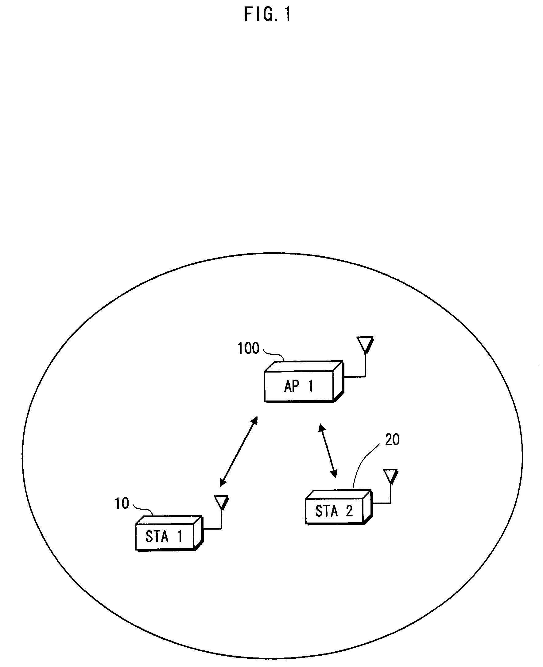
[0073]First is a description of a wireless LAN communication system pertaining to embodiment 1 of the present invention, with reference to FIG. 1.

[0074]As shown in FIG. 1, the wireless LAN communication system of embodiment 1 includes a communication terminal 10 (STA 1), a communication terminal 20 (STA 2), and an access point 100 (AP 1), which is a wireless LAN base station.

[0075]The wireless LAN communication system conforms to the IEEE 802.11 standard, and is operated in accordance with access control by the CSMA / CA method.

[0076]The access point 100 is an apparatus that controls the wireless LAN, and is connected to a larger-scale network such as another LAN or the Internet, which is not depicted in FIG. 1. While set to an infrastructure mode, the access point 100 relays communication when the communication terminals 10 and 20 on the network perform communication with each other and with communication terminals on another wireless LAN.

[0077]1-1. CSMA / CA

[0078]The ...

embodiment 2

[0115]The following describes embodiment 2 of the present invention with reference to the drawings.

[0116]1. Overview

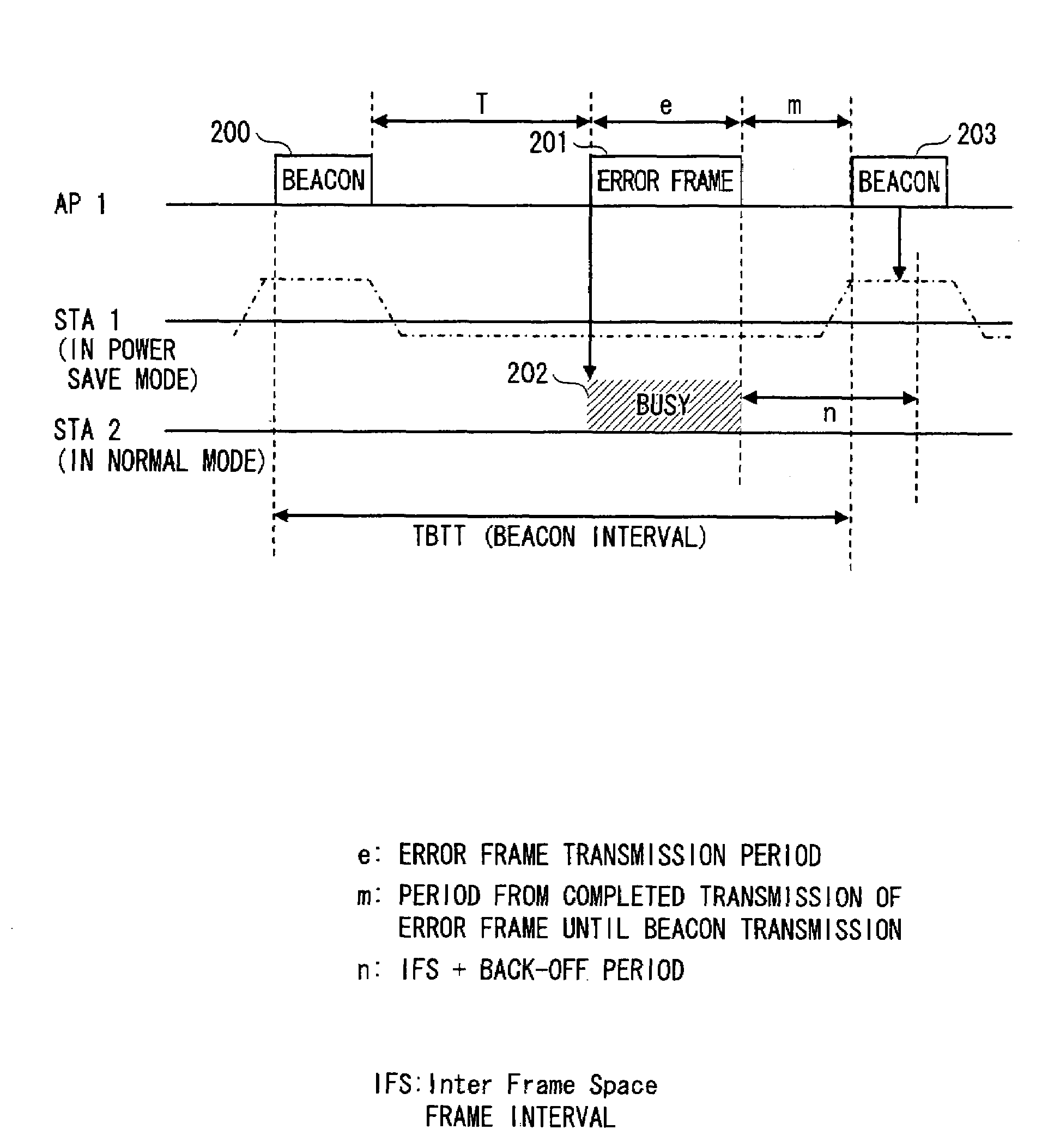
[0117]Whereas the access point 100 transmits an error frame ahead of the beacon signal in embodiment 1, in embodiment 2 the access point 100 transmits a CTS frame specified in the IEEE 802.11 standard.

[0118]2. Structure of AP 1

[0119]The following describes only aspects of the structure that differ from embodiment 1.

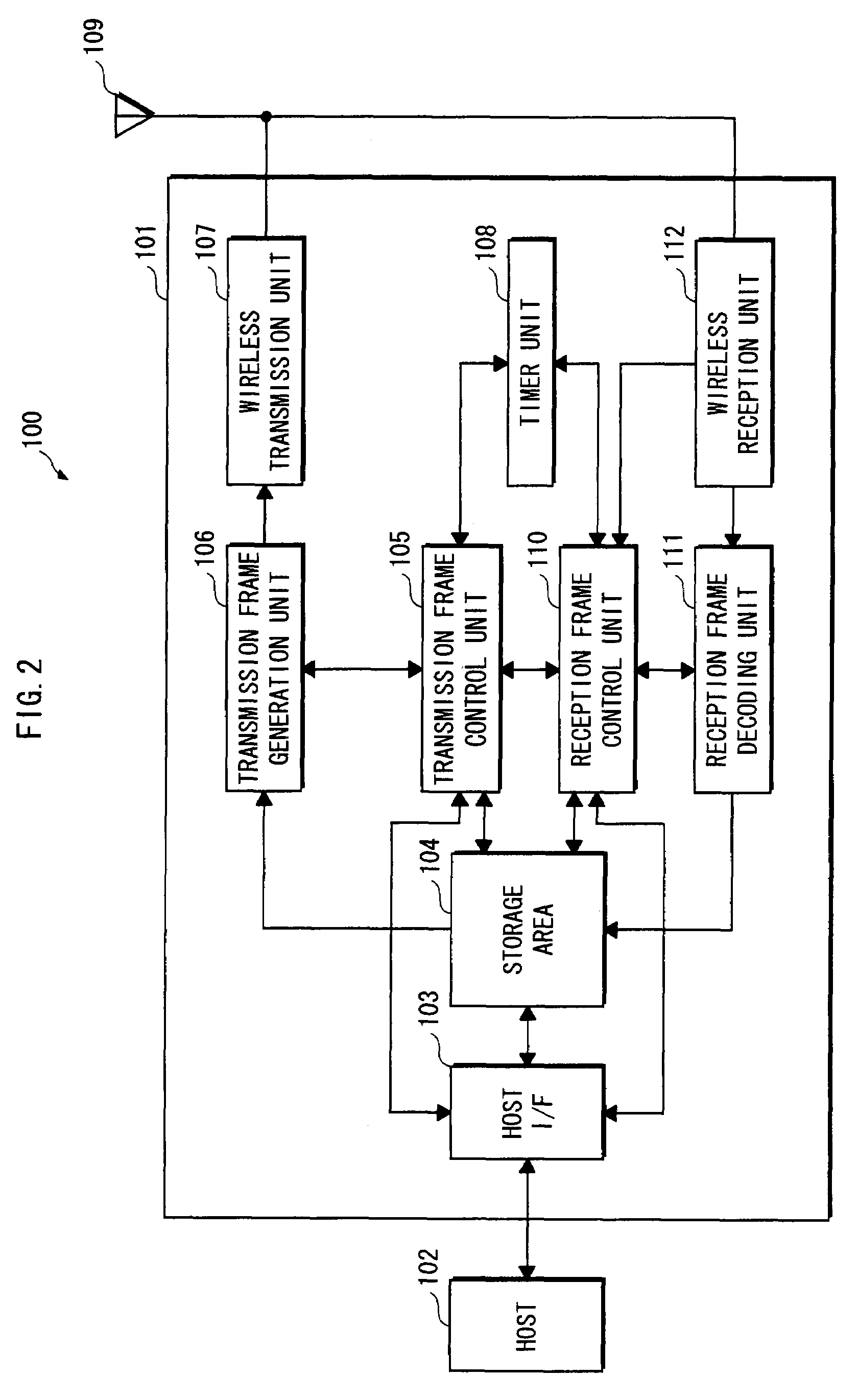
[0120]Upon the timer unit 108 clocking a time T at which the CTS frame is to be transmitted ahead of the beacon signal, the transmission frame control unit 105 determines a NAV to be included in the CTS frame, generates CTS frame data that includes the determined NAV, and sends the generated data to the transmission frame generation unit 106.

[0121]The timer unit 108 conforms to the IEEE 802.11 standard, and clocks the predetermined cycle TBTT for cyclical transmission of the beacon signal, and a predetermined cycle T for transmission of the CTS frame ahead o...

embodiment 3

[0134]The following describes embodiment 3 of the present invention with reference to the drawings.

[0135]1. Overview

[0136]Whereas the access point 100 transmits an error frame ahead of the beacon signal in embodiment 1, in embodiment 3 the access point 100 transmits a PLCP header specified in the IEEE 802.11 standard.

[0137]As shown in FIG. 5A, according to the IEEE 802.11 standard, a PLCP preamble 400 necessary for reception synchronization processing as well as a PLCP header 401 containing information such as a transfer rate and a frame length are attached to transmission data 402 in the physical layer.

[0138]2. Structure of AP 1

[0139]The following describes only aspects of the structure that differ from embodiment 1.

[0140]Upon the timer unit 108 clocking a time T at which the PLCP header is to be transmitted ahead of the beacon signal, the transmission frame control unit 105 determines a Length to be included in the PLCP header, generates a PLCP header that includes the determined ...


PUM


Abstract

The present invention relates to a wireless LAN (Local Area Network) communication system. Upon a timer unit 108 clocking a predetermined time T after an access point 100 has transmitted a beacon signal 200, a transmission frame control unit 105 generates a CTS frame 301, and transmits an error frame 401 via a transmission frame generation unit 106, a wireless transmission unit 107 and an antenna 109. Accordingly, upon receiving the CTS frame 301, a communication terminal 20 ceases transmitting data for a NAV (Network Allocation Vector, transmission prohibition interval) period in accordance with IEEE 802.11 standard.

Description

BACKGROUND OF INVENTION[0001]1. Field of the Invention[0002]The present invention relates to a wireless LAN (Local Area Network) communication system, and in particular to communication terminals and a relay apparatus that relays communication between the communication terminals in the communication system.[0003]2. Related Art[0004]In recent years, wireless LANs have come to include a communication mode called “infrastructure mode” in which two or more communication terminals perform communication with each other via a specified relay apparatus (hereinafter, called an access point) that controls the network.[0005]IEEE (Institute of Electrical and Electronic Engineers) 802.11 is a typical wireless LAN standard. The IEEE 802.11 standard is described in the following document:[0006]“International Standard ISO / IEC 8802-11: 1999 (E) ANSI / IEEE Std 802.11, 1999 Edition, Part 11: Wireless LAN Media Access Control (MAC) and Physical Layer (PHY) Specifications”[0007]In the IEEE 802.11 standar...

Claims


Application Information

Patent Timeline
Patent Type & Authority Patents(United States)
IPC IPC(8): H04B3/36H04B7/14
CPCH04B7/15528H04W52/0229H04W48/08H04W74/0816H04W88/04Y02B60/50Y02D30/70
Inventor NISHIO, YUKIIRIE, MASATAKA
Owner PANASONIC SEMICON SOLUTIONS CO LTD
Why Eureka
Try Eureka