Waste heat utilization device and control method thereof

a technology of waste heat and waste heat, which is applied in the direction of machines/engines, lighting and heating apparatus, machine operation modes, etc., can solve the problems of deteriorating the fuel consumption efficiency of the engine, energy loss in the whole cycle of waste heat,

Inactive Publication Date: 2010-04-06
DENSO CORP
View PDF5 Cites 20 Cited by
  • Summary
  • Abstract
  • Description
  • Claims
  • Application Information

AI Technical Summary

Benefits of technology

[0011]In view of the foregoing problems, it is a first object of the present invention to provide a waste heat utilization device which can control the energy balance to be always plus regardless of the cooling load of a refrigeration cycle in a combination operation where the refrigeration cycle and a Rankine cycle are simultaneously operated.
[0012]It is a second object of the present invention to provide a control method for controlling a waste heat utilization device, which can control the energy balance to be always plus regardless of the cooling load of a refrigeration cycle in a combination operation where the refrigeration cycle and a Rankine cycle are simultaneously operated.
[0014]In the waste heat utilization device, the control unit performs a continuation control of the Rankine cycle, in which the Rankine cycle is continuously operated regardless of an operation state of the compressor, when a load of the refrigeration cycle is lower than a predetermined load. In contrast, the control unit performs an intermittent control of the Rankine cycle, in which the Rankine cycle is intermittently operated in accordance with the operation state of the compressor such that the mechanical energy recovered by the expansion unit is larger than a driving energy of the compressor. Accordingly, in a case where the load of the refrigeration cycle is lower than the predetermined load, because the mechanical energy recovered by the Rankine cycle is larger than the driving energy of the compressor, the energy balance between the recovered mechanical energy and the driving energy of the compressor can be made plus while the Rankine cycle can be continuously operated. As a result, the waste heat of the heat generating unit can be effectively used. Furthermore, in a case where the load of the refrigeration cycle is higher than the predetermined load, by performing the intermittent control of the Rankine cycle, it can prevent the mechanical energy recovered by the expansion unit from being lower than the driving energy of the compressor. As a result, the energy balance between the recovered mechanical energy and the driving energy of the compressor can be made plus, and the waste heat of the heat generating unit can be effectively used.
[0015]According to another aspect of the present invention, a control method of a waste heat utilization device includes: a step of performing a continuation control of a Rankine cycle, in which the Rankine cycle is continuously operated regardless of an operation state of a compressor of a refrigeration cycle, when a load of the refrigeration cycle is lower than a predetermined load; and a step of performing an intermittent control of the Rankine cycle, in which the Rankine cycle is intermittently operated in accordance with the operation state of the compressor such that the mechanical energy recovered by an expansion unit is larger than a driving energy of the compressor. Accordingly, regardless of the load of the refrigeration cycle, the energy balance can be made always plus even in a combination operation where both the refrigeration cycle and the Rankine cycle are simultaneously operated, and the waste heat from the heat generating unit can be effectively recovered.

Problems solved by technology

However, in a case where cooling load is large in the refrigeration cycle in the summer season, when the refrigeration cycle and the Rankine cycle are simultaneously operated in the waste heat utilization device, energy loss may be caused in the whole cycle of the waste heat utilization device even when waste heat is recovered in the Rankine cycle.
As shown in FIG. 16, in the combination operation of the waste heat utilization device, even when the energy is recovered in the Rankine cycle, the energy balance between the recovered energy E2 and the driving energy E1 becomes minus when the cooling load is larger than a predetermined value, thereby deteriorating the fuel consumption efficiency in the engine.

Method used


Image

  • Waste heat utilization device and control method thereof
  • Waste heat utilization device and control method thereof
  • Waste heat utilization device and control method thereof

Examples


first embodiment

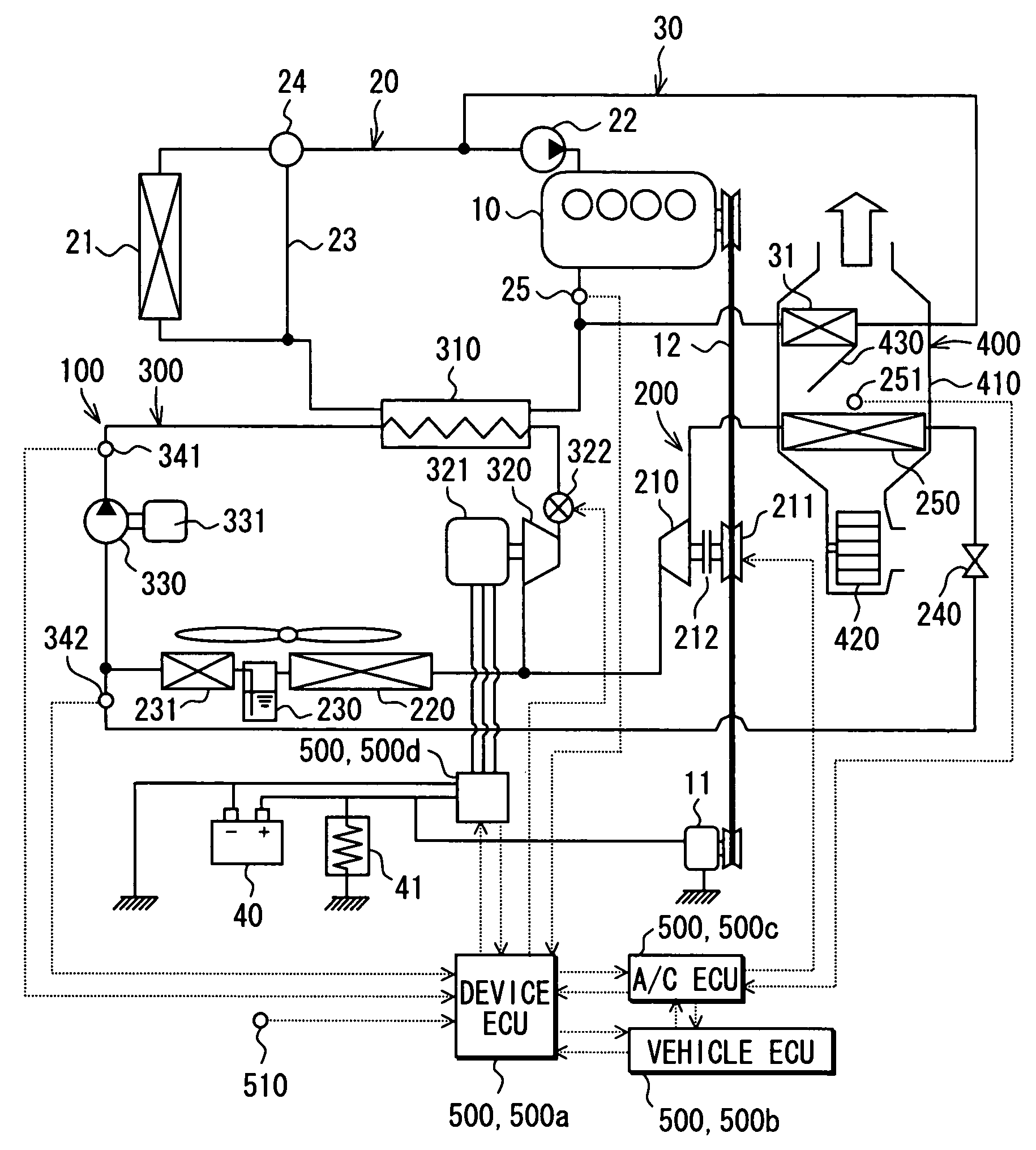
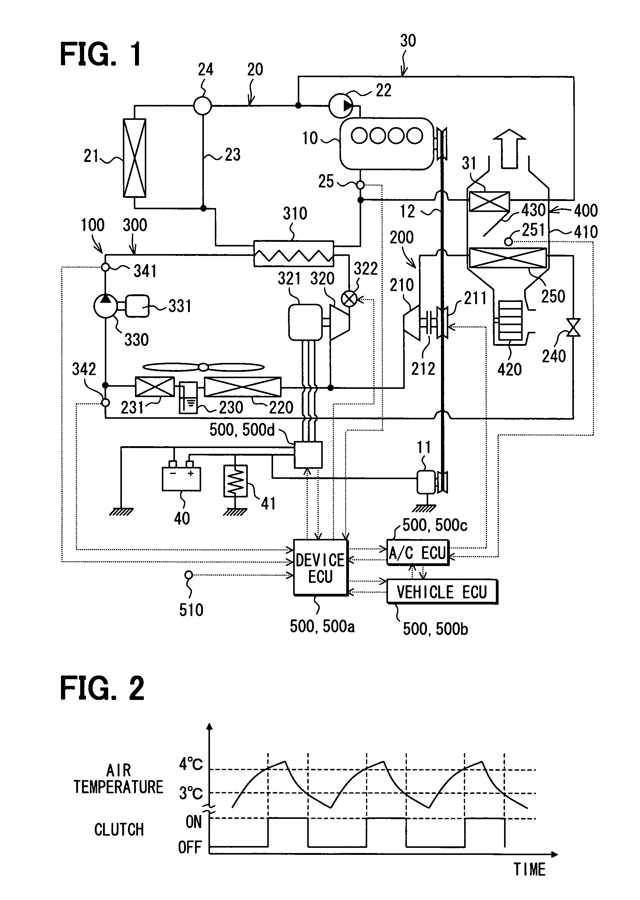
[0035]A first embodiment of the present invention will be now described with reference to FIGS. 1 to 5. In this embodiment, a waste heat utilization device 100 (cycle system) is typically used for a vehicle using an internal combustion engine 10 as a vehicle driving source. The waste heat utilization device 100 is constructed with a refrigeration cycle 200, a Rankine cycle 300 having a generator 321, and a control unit 500 (500a, 500b, 500c, 500d) for controlling operation of the refrigeration cycle 200 and the Rankine cycle 300. A part of components of the refrigeration cycle 200 is used in common with the Rankine cycle 300.

[0036]The engine 10 is a water-cooled internal combustion engine, and is an example of a heat generating unit in this embodiment. As shown in FIG. 1, a radiator circuit 20 and a heater circuit 30 are provided for the engine 10. The Engine 10 is cooled by engine-cooling water circulating in the radiator circuit 20, and air-conditioning air is heated using the eng...

second embodiment

[0081]A second embodiment of the present invention will be now described with reference to FIGS. 6 to 10. In a waste heat utilization device 100 of the second embodiment, a variable displacement compressor 210A is used instead of the fixed displacement compressor 210, as compared with the first embodiment. That is, the variable displacement compressor 210A changes a slant angle of its slant plate so as to adjust its discharge capacity per rotation. Therefore, in the second embodiment, the electromagnetic clutch 212 of the above-described first embodiment is omitted. Thus, a control method for controlling the compressor 210A in the combination operation of the refrigeration cycle 200 and the Rankine cycle 300 is different from that of the above-described first embodiment.

[0082]The compressor 210A has a variable discharge capacity that is changeable continuously from 0% to 100% when a maximum discharge capacity to be dischargeable is 100%. When the discharge capacity of the compressor...

third embodiment

[0093]In the above-described first and second embodiments, the cooling load is determined based on the outside air temperature T(AM). In the third embodiment, the cooling load is determined by combining information used for the control of the engine 10 and information used for the control of the refrigeration cycle 200.

[0094]The vehicle speed can be used for the control information of the engine 10. Generally, as the vehicle speed increases, the wind air flowing into the condenser 220 is increased so as to facilitate heat exchange with the refrigerant. Therefore, as the vehicle speed increases, the cooling load of the refrigeration cycle 200 becomes smaller.

[0095]Furthermore, as the control information of the refrigeration cycle 200, a solar radiation amount T(S) entering into the passenger compartment, an actual inside temperature T(IN) of the passenger compartment and a set temperature T(SET) can be used in addition to the outside air temperature T(AM). The cooling load is changed...


PUM


Abstract

A waste heat utilization device includes a refrigeration cycle having a compressor, a Rankine cycle using a condenser in common with the refrigeration cycle, and a control unit which controls operation of the refrigeration cycle and the Rankine cycle. The control unit performs a continuation control of the Rankine cycle, in which the Rankine cycle is continuously operated regardless of an operation state of the compressor, when a load of the refrigeration cycle is lower than a predetermined load. In contrast, the control unit performs an intermittent control of the Rankine cycle, in which the Rankine cycle is intermittently operated in accordance with the operation state of the compressor such that the mechanical energy recovered by the expansion unit is larger than a driving energy of the compressor.

Description

CROSS REFERENCE TO RELATED APPLICATION[0001]This application is based on Japanese Patent Application No. 2006-049291 filed on Feb. 24, 2006, the contents of which are incorporated herein by reference in its entirety.BACKGROUND OF THE INVENTION[0002]1. Field of the Invention[0003]The present invention relates to a waste heat utilization device and a control method thereof. For example, the waste heat utilization device recovers power by using waste heat of a heat generating unit, and can be suitably used for a vehicle having an internal combustion engine.[0004]2. Description of the Related Art[0005]A waste heat utilization device is described in JP-A-2005-307951 (corresponding to US 2005 / 0235670 A1), for example. The waste heat utilization device includes a refrigeration cycle for air-conditioning, and a Rankine cycle that recovers waste heat from a heat generating unit such as an internal combustion engine. The refrigeration cycle includes a compressor that is driven by power of the...

Claims


Application Information

Patent Timeline
Patent Type & Authority Patents(United States)
IPC IPC(8): F25B27/02
CPCB60H1/00885F01K13/02F01K25/08F25B27/02F01K23/065B60H2001/00928B60H2001/00949B60H2001/3297Y02T10/166F25B9/06F25B2400/141Y02T10/16Y02T10/12Y02A30/274
Inventor INABA, ATSUSHI
Owner DENSO CORP
Why Eureka
Try Eureka