Method and apparatus for using excess heat from power plant flue gas to dry biomass fuel

a technology of biomass fuel and flue gas, which is applied in the direction of drying machines with progressive movements, combustion types, furnaces, etc., can solve the problems of environmental problems, inefficiency of existing drying equipment, and high generation cost of existing drying equipment, and achieve low energy consumption and high drying efficiency.

Active Publication Date: 2019-07-02
ZHONGYING CHANGJIANG INTERNATIONAL NEW ENERGY INVESTMENT CO LTD
View PDF7 Cites 0 Cited by
  • Summary
  • Abstract
  • Description
  • Claims
  • Application Information

AI Technical Summary

Benefits of technology

[0009]In view of the above-described problems, it is one objective of the invention to provide a method and a device for drying biomass fuel using waste heat of flue gas from a power plant that feature relatively high drying efficiency and relatively low energy consumption.
[0027]2. The waste heat recovery of flue gas from a power plant is associated with the high-temperature, medium-temperature, and low-temperature drying of biomass fuel, and the biomass fuel is dried in multiple stages by high-temperature and low-temperature dry air, therefore making the most of energy, improving the drying efficiency, saving energy, and reducing emission. The cost of energy consumption is reduced significantly. Meanwhile, land occupation, heavy workload, and environmental problems caused by open-air drying of biomass fuel is avoided.
[0028]3. As the waste heat in the flue gas is recovered stepwise, the sensible heat is effectively recovered, and the latent heat released from vapor condensation is fully utilized as well, thus improving the utilization efficiency of waste heat in the flue gas, lowering discharge of carbon dioxide and heat, and reducing pollution caused by flue gas and waste heat.
[0029]4. Multi-layer conveying belts and air cooler tubes are used to achieve continuous drying in three stages: high-temperature drying at high speed, medium-temperature drying at constant speed, and low-temperature drying at accelerated speed, thus the drying efficiency is improved, and fuel supply demand is satisfied. The biomass fuel exchanges heat and humidity with the high-temperature air and the low-temperature air on the multi-layer conveying belts. Transverse baffle plates are configured to separate belts in the drying room to form a first drying zone, a second drying zone, and a third drying zone, thus effectively preventing cross flow of the air at different temperatures, and further improving drying efficiency.
[0030]5. The utilization of the air cooler tubes including heat recovery, dehumidification, and cooling is creative. The air cooler tubes are a combination of adsorber, condenser, and evaporator, feature good heat and mass transfer effect, and require less transmission equipment, thus the air cooler tubes are low-cost, easy to manufacture and use.

Problems solved by technology

However, the drying method has the following disadvantages:1) The existing drying equipment is inefficient.2) The existing drying equipment contributes to high generation cost.3) The open-air drying occupies a large land area, involves heavy workload, and causes environmental problems.

Method used


Image

  • Method and apparatus for using excess heat from power plant flue gas to dry biomass fuel
  • Method and apparatus for using excess heat from power plant flue gas to dry biomass fuel
  • Method and apparatus for using excess heat from power plant flue gas to dry biomass fuel

Examples


Embodiment Construction

[0036]For further illustrating the invention, experiments detailing a method and a device for drying biomass fuel using waste heat of flue gas from a power plant are described below. It should be noted that the following examples are intended to describe and not to limit the invention.

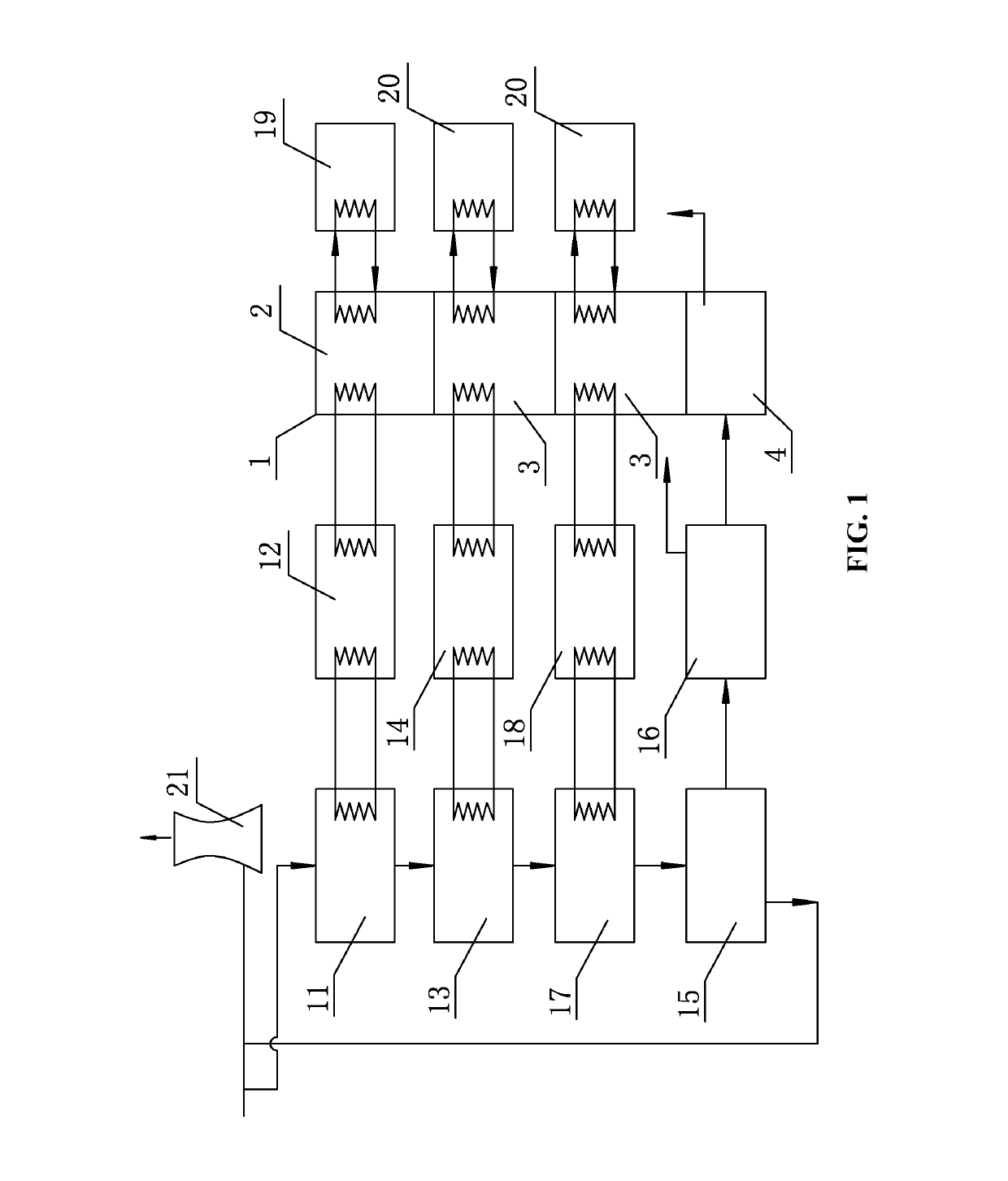
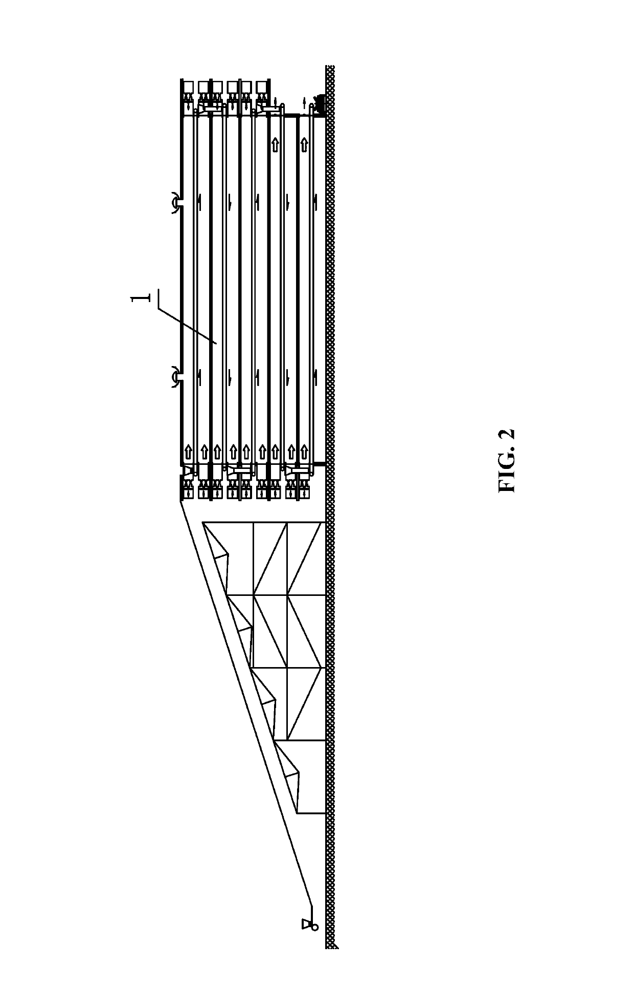
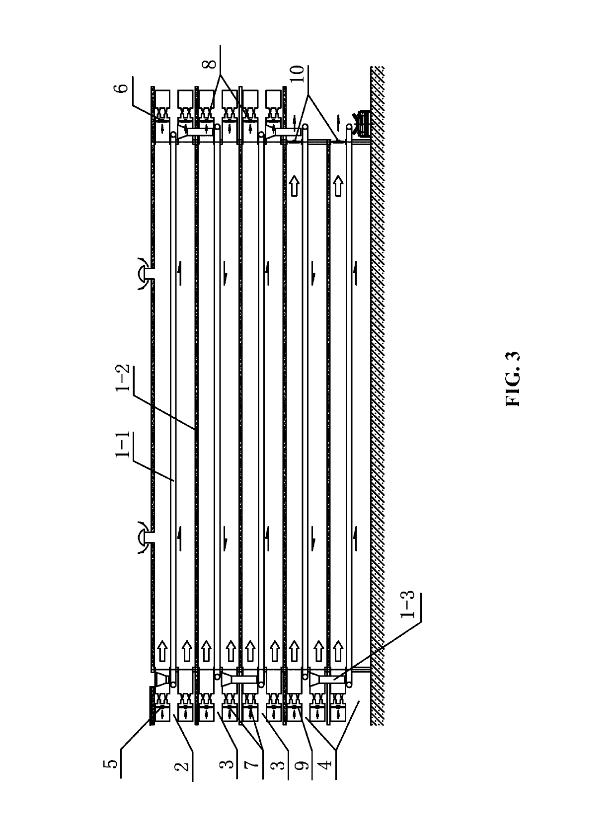
[0037]As shown in FIGS. 1-4, a device for drying biomass fuel using waste heat of flue gas from a power plant comprises a multi-layer dryer 1. The multi-layer dryer 1 comprises a drying room comprising multi-layer conveying belts 1-1. The multi-layer conveying belts are transversely disposed according to the scale of drying. The multi-layer conveying belts 1-1 are mesh belts or chain board belts which run on a round trip. The multi-layer conveying belts are mesh belts or chain board belts comprising between 45 and 65% of vent holes in area. The drying room comprises a plurality of two transverse baffle plates 1-2 which is parallel to the multi-layer conveying belts 1-1. The multi-layer conveying belts ...


PUM


Abstract

A method for drying biomass fuel using waste heat of flue gas from a power plant. The method includes: 1) stepwise recovering, by multi-stage condensation, sensible heat of flue gas; stepwise heating air using the sensible heat, to yield first-stage dry air and second-stage dry air; 2) convectively drying and dehydrating biomass fuel using the first-stage dry air having a temperature of between 150 and 180° C.; 3) further convectively drying and dehydrating the biomass fuel using the second-stage dry air having a temperature of between 80 and 100° C.; and 4) drying and dehydrating the biomass fuel using the third-stage dry air having a temperature of less than or equal to 25° C.

Description

CROSS-REFERENCE TO RELATED APPLICATIONS[0001]This application is a continuation-in-part of International Patent Application No. PCT / CN2015 / 092501 with an international filing date of Oct. 22, 2015, designating the United States, now pending, and further claims foreign priority benefits to Chinese Patent Application No. 201410578212.8 filed Oct. 24, 2014. The contents of all of the aforementioned applications, including any intervening amendments thereto, are incorporated herein by reference. Inquiries from the public to applicants or assignees concerning this document or the related applications should be directed to: Matthias Scholl P.C., Attn.: Dr. Matthias Scholl Esq., 245 First Street, 18th Floor, Cambridge, Mass. 02142.BACKGROUND OF THE INVENTION[0002]Field of the Invention[0003]The invention relates to a method and a device for drying biomass fuel using waste heat of flue gas from a power plant.[0004]Description of the Related Art[0005]Typically, biomass fuel for use in a powe...

Claims


Application Information

Patent Timeline
Patent Type & Authority Patents(United States)
IPC IPC(8): F23G5/04F23G5/44F26B21/14F26B17/08F26B15/18F23G5/46F26B17/02F26B23/00
CPCF23G5/04F23G5/46F26B15/18F26B17/02F26B17/08F26B21/14F26B23/001F23G5/444Y02P70/405F23G2201/101F23G2205/122F23G2206/10F23K2201/20F26B2200/02Y02P70/40Y02P70/10F26B3/06F26B21/04
Inventor CHEN, YILONGHU, SHUCHUANZHANG, YANFENG
Owner ZHONGYING CHANGJIANG INTERNATIONAL NEW ENERGY INVESTMENT CO LTD
Why Eureka
Try Eureka