Fuel cell system with a water holding member

a fuel cell and water holding member technology, applied in the field of fuel cell systems, can solve the problems of unnecessary water management control and complicated control, and achieve the effects of preventing the drying of a proton exchange membrane, preventing the generation of liquid droplets, and increasing tolerance (or robustness) to water balan

Inactive Publication Date: 2010-04-06
CANON KK
View PDF9 Cites 0 Cited by
  • Summary
  • Abstract
  • Description
  • Claims
  • Application Information

AI Technical Summary

Benefits of technology

[0013]According to the constitution of the present invention, it is possible to prevent the drying of a proton exchange membrane and to prevent the generation of liquid droplets at a hydrogen tank surface which blocks the supply of air, at the same time. Further, the tolerance (or robustness) to water balance (hydrologic balance) increases and complicated control for management of water becomes unnecessary. Accordingly, further reduction in size of a fuel cell system becomes possible and it is possible to provide a small fuel cell system for a small electric equipment.

Problems solved by technology

Further, the tolerance (or robustness) to water balance (hydrologic balance) increases and complicated control for management of water becomes unnecessary.

Method used


Image

  • Fuel cell system with a water holding member
  • Fuel cell system with a water holding member
  • Fuel cell system with a water holding member

Examples


Embodiment Construction

[0022]Embodiments of the present invention will be described with reference to the attached drawings.

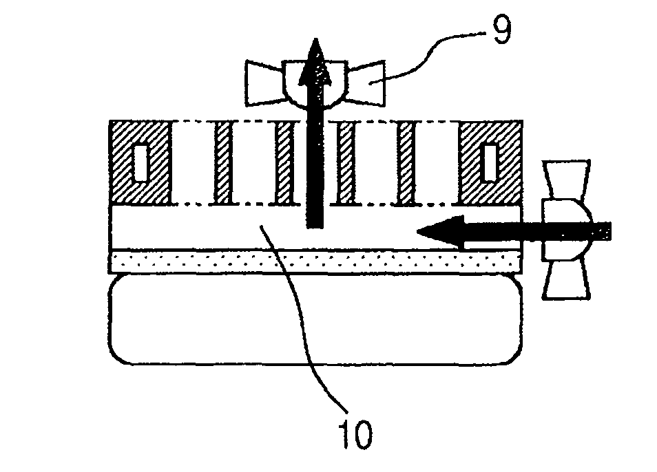
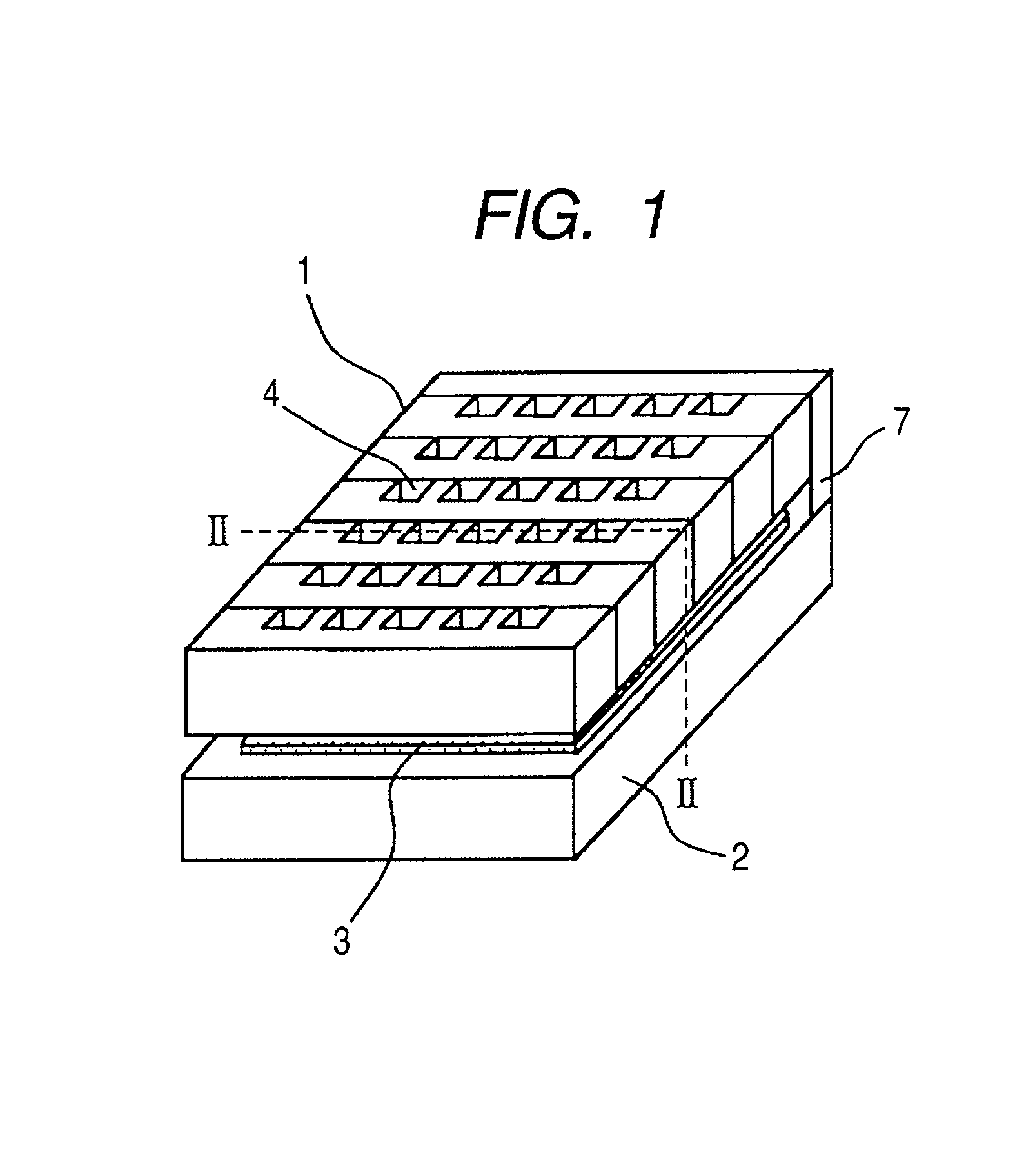
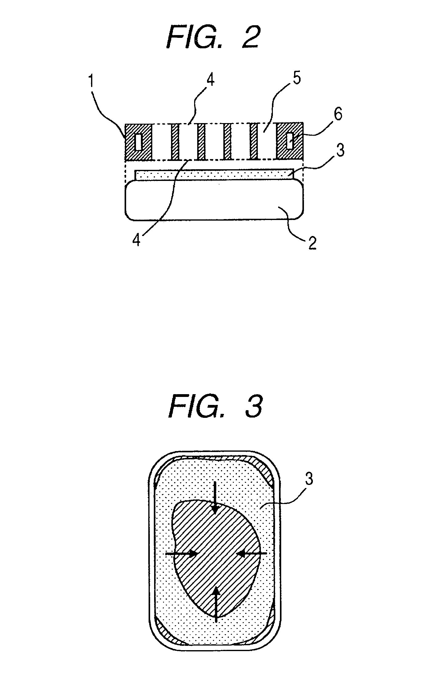
[0023]FIG. 1 is a schematic perspective view of a fuel cell system in accordance with one embodiment of the present invention, and FIG. 2 is a schematic cross-sectional view taken along line II-II in FIG. 1. As shown in the figures a fuel cell stack 1 and a hydrogen tank 2 are disposed so as to face each other. In the fuel cell stack 1 are provided air holes 4 for supplying air of the atmosphere to an oxidizer electrode. The air holes are provided at the atmosphere side and at the hydrogen tank side. On a fuel cell side surface of the hydrogen tank 2 is provided a water holding (or retaining) member 3.

[0024]The fuel cell stack is configured by alternately stacking fuel cells and separators on each other. Each fuel cell has a membrane electrode assembly (MEA) formed by providing, respectively, a fuel electrode catalyst layer and an oxidizer electrode catalyst layer on both surfaces of...


PUM

PropertyMeasurementUnit
temperatureaaaaaaaaaa
thickaaaaaaaaaa
sizeaaaaaaaaaa

Abstract

There is provided a fuel cell system which can prevent the drying of a proton exchange membrane and prevent the generation of liquid droplets at a hydrogen tank surface which blocks the supply of air, at the same time, and which includes a hydrogen tank, a fuel cell stack disposed such that a first air hole thereof faces the hydrogen tank and a second air hole thereof is open to the atmosphere, and a water holding member provided on a surface of the hydrogen tank facing the first air hole of the fuel cell stack, for collecting and holding water generated in the fuel cell stack.

Description

BACKGROUND OF THE INVENTION[0001]1. Field of the Invention[0002]The present invention relates to a fuel cell system.[0003]2. Description of the Related Art[0004]Japanese Patent Application Laid-Open No. H10-092456 discloses, as a fuel cell system for a small electric equipment, a configuration in which proton exchange membrane fuel cells (or polymer electrolyte fuel cells) are driven with hydrogen supplied from a hydrogen storage alloy and air. The hydrogen releasing process of a hydrogen storage alloy is an endothermic reaction, so that the temperature of the hydrogen storage alloy decreases when supplying the hydrogen fuel. Because the hydrogen releasing ability of the hydrogen storage alloy is lowered with the decrease of the temperature of the alloy, it is necessary to heat the hydrogen storage alloy in order to assure a sufficient flow rate of hydrogen.[0005]On the other hand, because the power generation by means of a fuel cell is accompanied by heat generation, it has been pr...

Claims


Application Information

Patent Timeline
Patent Type & Authority Patents(United States)
IPC IPC(8): H01M2/00H01M2/14
CPCH01M8/04089H01M8/04126H01M8/04208H01M8/04171Y02E60/50H01M8/241H01M8/2457H01M8/2484
Inventor MOGI, SATOSHIUEDA, KAZUYUKISHIBATA, MASAAKI
Owner CANON KK
Why Eureka
Try Eureka