Modulating transmission timing for data communications

a technology of data communication and transmission timing, applied in the field of digital communication, can solve the problems of replacing less efficient modulation methods, and achieve the effects of simple modification, increased throughput, and increased telemetry

Active Publication Date: 2010-04-06
MOBIT TELECOM
View PDF4 Cites 17 Cited by
  • Summary
  • Abstract
  • Description
  • Claims
  • Application Information

AI Technical Summary

Benefits of technology

[0023]Utilizing signals arrived from a Global Navigation Satellite System (GNSS), such as the USA GPS, can significantly assist in accurately and synchronously determining the nominal transmission timing and / or nominal receiving timing. The GNSS timing signals provide a universal common timing base, available everywhere, which the transmitter and the receiver can acquire and synchronize with.
[0029]The present method may employ a further variation, based on relative measurements between consecutive transmissions and receptions. According to this variation, the nominal transmission timing is shifted after each transmission by the modulated time period and the nominal receiving timing is shifted after each reception by the demodulated time period. In other words, after each transmission, the nominal transmission timing is preset, referring to the last time of transmission as a new base for the nominal transmission. Then, the receiver may decode the transmitted symbol by measuring the time difference between consecutive receptions. This way, the receiver task is much easier, since it does not require to consider the propagation delay (assuming that the distance between transmitter and receiver is not significantly changed between consecutive transmissions). Yet, such a variation is more sensitive to noise, and if one transmission is not detected, the next symbol cannot be decoded.
[0037]The present method can be applied to a special case, where the transmitter is a radio beacon (i.e. radio that transmits data automatically, not necessarily operated by a human) and its transmitted signal is configured to communicate telemetry; then, the transmitted symbols are configured to augment this telemetry. This way, conventional radio beacons can easily be upgraded by the present invention, increasing their throughput by relatively simple modifications, possibly even just in software.

Problems solved by technology

Over the years, less efficient modulation methods phased out and were been replaced by more efficient modulation techniques, usually digital.

Method used


Image

  • Modulating transmission timing for data communications
  • Modulating transmission timing for data communications
  • Modulating transmission timing for data communications

Examples


first embodiment

[0059]Microprocessors are also very known products in the art, as a skilled person probably appreciates. the invention relates to a microcontroller from the MSP430 family, provided by Texas Instruments (TI). For reference, one may look at—http: / / focus.ti.com / mcu / docs / mcuprodoverview.tsp?sectionId=95&tabId=140&familyId=342

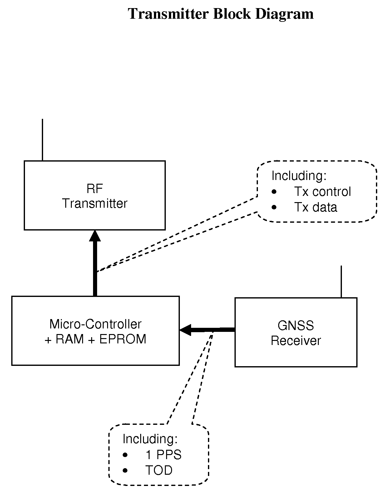
[0060]Then, according to this first embodiment, the microprocessor activates the transmitter every 10 seconds, exactly at the 1 PPS transition associated with the TOD indicating that the least significant number of seconds is changing from 9 to 0 (from 9 to 10, from 19 to 20, from 59 to 0, etc.).

[0061]FIG. 7 depicts the Receiver Block Diagram, according to the first embodiment of the invention. As shown, the receiver comprises a microprocessor, which among other tasks is responsible to determine the receiving timing, coupled to a GNSS (GPS) receiver and to an RF receiver. According to this first embodiment, the microprocessor uses the 1 PPS and TOD information provi...

second embodiment

[0070]According to the invention, the nominal time interval between consecutive transmissions is set to 50 s, yet only 10% of this time interval is used for time modulation. Then, the unique periods of time used for the modulation are set between minus half of this percentage of time interval, i.e. −2.5 s, to plus half of this percentage of time interval, i.e. +2.5 s. Subsequently, the difference between close values of unique time periods in the encoding table is set substantially equal to 50 s×10%=5 s, divided by the number of symbols in the encoding table.

[0071]The second embodiment of the invention is related to the Cospas-Sarsat SAR satellite system. This embodiment is intended to comply with the Cospas-Sarsat requirements yet also improve the system performance. So a nominal transmission timing of one transmission every 50 seconds is according to Cospas-Sarsat requirements, as well as the transmission timing accepted change between −2.5 s to +2.5 s. Using a GPS receiver at the...

third embodiment

[0083]According to this aspect of the invention, the relative time modulation is used along with the Greenwich Time Signal (GTS), popularly known as the pips. The GTS is a series of six short tones broadcast by many BBC radio stations at the end of each hour to mark the precise start of the following hour. It normally comprises six pips in total, which occur on the 5 seconds leading up to the hour and on the hour itself. Each pip is a 1 kHz tone which, for the five leading pips, lasts a tenth of a second, while the final pip lasts half a second. The hour changes at the very beginning of the last long pip. The time interval between the beginnings of successive pips is normally 1 second. Then, according to the present invention, one bit of information is modulated on this GTS timing, to indicate a tsunami alert. Accordingly, if no tsunami is forecast, the GTS is kept as normal; yet, to alert for a possible near tsunami, the 3rd pip of the GTS is broadcast 0.5 seconds after the 2nd pip...


PUM


Abstract

A modulation method, applicable for augmentation of present art modulated signals. The method, for communicating data from a transmitter to a receiver, is based on periodical burst transmissions, set at a nominal timing, of signals which are either pure carriers or already modulated by data (e.g. ASK, FSK, PSK). Knowing the transmission timing and assessing the propagation delay, the receiver can estimate the nominal reception timing of these periodical transmissions. Modifying the nominal timing of a transmission, by a specific time period, is used to communicate a symbol between the transmitter and the receiver, according to a predefined encoding table which associates between a symbol and a unique time period. According to one embodiment of the invention, the transmitter is a distress radio beacon, configured to report its position upon activation, in periodical data burst transmissions, to ground stations through satellites. The present method is used to augment this report, complying with the present beacon specifications, yet providing a finer resolution of the reported coordinates. According to one embodiment, the position resolution is improved approximately from 125 to 8 meters.

Description

BACKGROUND OF THE INVENTION[0001]The present invention relates to the art of digital communications, particularly modulation and encoding methods, specifically in which the information to be transmitted is conveyed by means of the relative position of pulses in a series of transmitted pulses or the time or spacing between pulses.[0002]Communication, as well known, is the process of conveying information (also referred to as “data” hereinafter), from a sender, or more technically speaking a transmitter, to a receiver, via a medium. Such a medium can be a twisted pair of copper wires, a laser beam or an RF carrier, to name a few. Information can be encoded in various ways, such as an analog voltage representing human sound amplitude and frequency and pitch, or a series of digital pulses representing the geographical coordinates of a specific location, and so on. Typically, information is communicated by modulating a carrier wave, e.g. changing its amplitude or frequency or phase, in a...

Claims


Application Information

Patent Timeline
Patent Type & Authority Patents(United States)
IPC IPC(8): H03K7/04
CPCG01S5/0027G01S5/0226H04L25/493G01S19/17H03K7/04G01S19/13
Inventor KATZ
Owner MOBIT TELECOM
Why Eureka
Try Eureka