Providing memory test patterns for DLL calibration

a memory test and dll technology, applied in the field of electronic memory, can solve the problems of poor representation of the bus under worst case switching conditions, limited and generic test patterns stored in the current dll calibration method, and the low utilization rate of the high-speed memory bus, so as to achieve the optimal delay calibration and more accurate dll calibration

a memory test and dll technology, applied in the field of electronic memory, can solve the problems of poor representation of the bus under worst case switching conditions, limited and generic test patterns stored in the current dll calibration method, and the low utilization rate of the high-speed memory bus, so as to achieve the optimal delay calibration and more accurate dll calibration

US7694202B2Inactive Publication Date: 2010-04-06ROUND ROCK RES LLC

Image

  • Providing memory test patterns for DLL calibration
  • Providing memory test patterns for DLL calibration
  • Providing memory test patterns for DLL calibration

Examples


Embodiment Construction

[0019]Reference will now be made in detail to some embodiments of the present disclosure, examples of which are illustrated in the accompanying drawings. It is to be understood that the figures and descriptions of the present disclosure included herein illustrate and describe elements that are of particular relevance to the present disclosure, while eliminating, for the sake of clarity, other elements found in typical solid-state memories or memory-based systems. It is noted at the outset that the terms “connected”, “connecting,”“electrically connected,” etc., are used interchangeably herein to generally refer to the condition of being electrically connected.

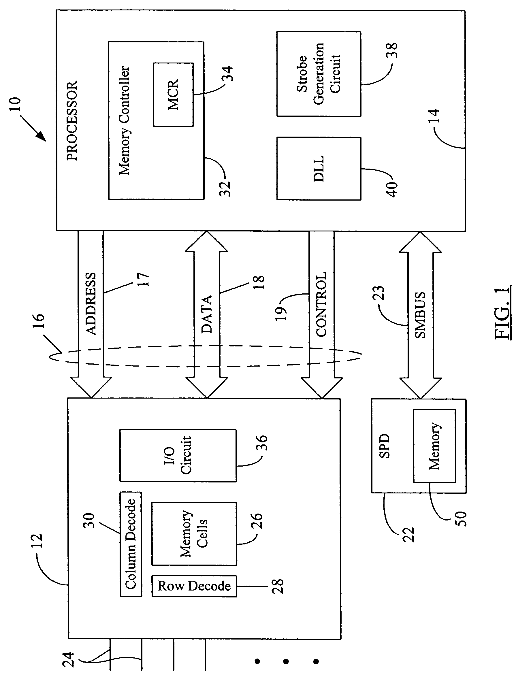
[0020]FIG. 1 is block diagram showing an exemplary system 10 for DLL calibration including a memory chip or memory device 12 in communication with a processor 14 via a system bus 16. FIG. 1 also shows an SPD circuit 22 (described in more detail later) in communication with the processor 14 via an SMBus (System Management Bus) 23...


PUM


Abstract

A system and method to provide memory test patterns for the calibration of a delay locked loop (DLL) using a pseudo random bit sequence (PRBS) stored in a serial presence detect (SPD) circuit memory. The test bits stored in the SPD memory are transferred to a memory controller register (MCR) and implemented on the system data bus as test patterns that closely simulate run-time switching conditions on the system bus, so as to allow more accurate calibration of the DLL. Test data write / read operations may be performed while signals for the test patterns are present on various bit lines in the data bus so as to allow for accurate determination or adjustment of the value for the delay to be provided by the DLL to the strobe signals during memory data reading operations at run time. Memory chips may also be tested over an operating range of values using the generated test patterns.

Description

REFERENCE TO RELATED APPLICATION[0001]The disclosure in the present application is related to the disclosure provided in the commonly-assigned United States patent application titled “Generation of Memory Test Patterns for DLL Calibration,” filed concurrently herewith.BACKGROUND[0002]1. Field of the Disclosure[0003]The present disclosure generally relates to an electronic memory and, more particularly, to providing a test pattern of pseudo random bit sequence (PRBS) during calibration of a delay locked loop (DLL) and during memory testing.[0004]2. Brief Description of Related Art[0005]Memory devices are widely used in many electronic products and computers to store data. A memory device includes a number of memory cells, each cell storing one bit of data. The data stored in the memory cells can be read during a read operation.[0006]One type of memory device includes a reference signal to accompany data signals during a read operation. The reference signal, commonly known as a “strob...

Claims


Application Information

Patent Timeline
06 Apr 2010
Publication
US7694202B2
IPC
G01R31/28; G06F7/02; G06F12/00; G11C7/00; G11C7/10; G11C29/02
CPC
G11C7/1072; G11C7/222; G11C29/028; G11C29/50012; G11C29/02; G11C2207/2254
Inventors
SWANSON, TRAVIS E.; ROONEY, JEFFREY J.