Imaging positioning system having robotically positioned D-arm

a positioning system and robotic technology, applied in the field of patient imaging systems, can solve the problems of limited orientation of imaging views, limited space within the treatment room, and risk of disturbing alignment, so as to achieve convenient positioning and further precision in operation.

Inactive Publication Date: 2010-04-13
FIRST MIDWEST BANK +1
View PDF21 Cites 22 Cited by
  • Summary
  • Abstract
  • Description
  • Claims
  • Application Information

AI Technical Summary

Benefits of technology

[0019]In one embodiment of the present invention, the imaging system utilizes a selectively compliant articulated robot arm (SCARA) type robot that provides five rotations and one linear translation axis. To maximize the available space within a treatment room, an embodiment of the present invention mounts the SCARA type robot in the ceiling of the treatment room. The SCARA type robot is then able to position the support structure so that the patient is within a volume defined by the support structure and the imaging components of the imaging equipment carried thereon. This allows imaging orientations along nearly every plane without requiring movement of the patient or the positioning table on which the patient has been secured.
[0029]Further yet, in some embodiments, the support ring is formed by a pair of segments or portions that are pivotally connected to one another. This allows the support ring to pivot between different pivoted states, namely a closed pivoted state where the support ring is a continuous ring and a second open pivoted state where the support ring is broken, thereby forming a mouth between the ends of the segments of the support ring. This allows the support ring to be more easily positioned about a patient. Once positioned about the patient, the support ring can be transitioned to the closed pivoted state where the support ring continuously surrounds an axis defined by the patient.

Problems solved by technology

Unfortunately, with such a mounted imaging system 10, the imaging views that are able to be taken are limited in orientation.
Any such movement of the table 19 once set up runs the risk of disturbing the alignment, i.e. patient's position and orientation, which will then need to be re-confirmed and set-up before further treatment is begun.
These camera structures also take up, and therefore limit, the available space within the treatment room, obstructing free movement of the technician or other medical personnel when in the treatment room.
Again, unfortunately, with this mounted imaging system arrangement, the imaging views that are able to be taken are limited in orientation to being angularly positioned about the particle beam.
Therefore, it is impossible in this system to align the imaging system, namely the x-ray source and x-ray detector, with the direction of particle beam.
While this arrangement permits some improved positioning of the imaging system over the previous systems, the imaging system of this radiotherapy system (i.e. both he x-ray source and the x-ray detector) the x-ray detector of the imaging system cannot be used to help align or check alignment of the particle beam relative to the target area.
Again, this unfortunately, requires additional set-up of another imaging device which inherently imports potential error in the alignment of the particle beam.
Unfortunately, rotating the entire support arm from the mounting point requires overcoming substantial rotational inertia due to the size and weight of the support arm and the moment arm created by offsetting the x-ray detector and x-ray source from the point of rotation of the support arm.

Method used


Image

  • Imaging positioning system having robotically positioned D-arm
  • Imaging positioning system having robotically positioned D-arm
  • Imaging positioning system having robotically positioned D-arm

Examples


Embodiment Construction

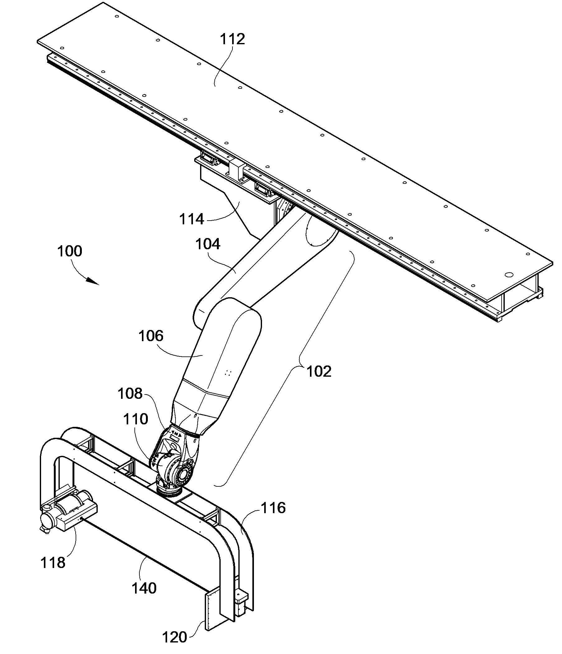
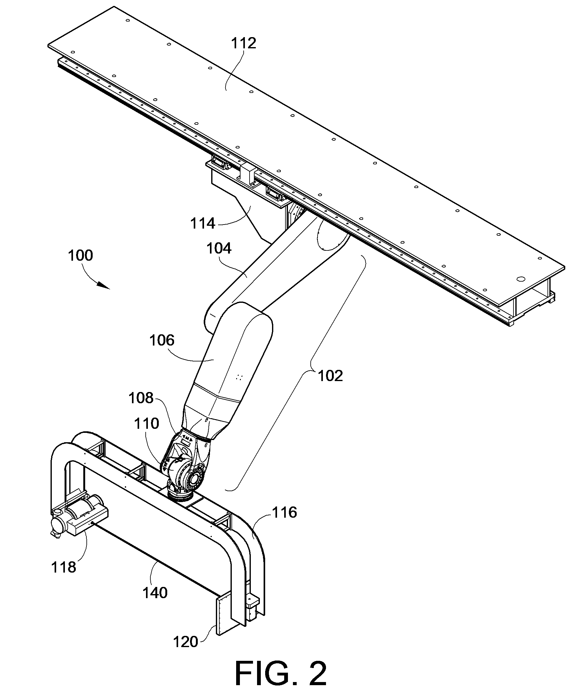
[0043]Turning now to FIG. 2, there is illustrated an embodiment of an imaging positioning system 100 constructed in accordance with the teachings of the present invention. While the following description will describe embodiments of the imaging positioning system in relation to its use in therapeutic radiation treatment operations and facilities, those skilled in the art will recognize that such embodiments and operating environments are provided by way of example only, and not by way of limitation.

[0044]In the illustrated embodiment, the imaging positioning system 100 utilizes a selectively compliant articulated robot arm (SCARA) type robot 102 that provides five rotations and one linear translation axis. Other embodiments of the present invention may utilize a standard six axis robot. The SCARA type robot 102 of the illustrated embodiment includes an upper arm portion 104, a lower arm portion 106, a wrist portion 108 and a coupling portion 110. Linear translation is provided along...


PUM


Abstract

An imaging positioning system having a robotically positioned support structure is provided. By utilizing a robotic arm, imaging along multiple planes within a patient treatment room without having to move the patient is provided. Such a configuration allows multiple axis x-ray imaging, cone beam CT acquisitions having a dynamic field of view, and PET imaging within the treatment room. Rotation of the imaging panel on the support structure allows the imaging system to simulate a gantry rotation when a fixed beam is used for treatment. Beam line x-ray imaging is also provided by tilting the imaging panel or by moving the support structure on which the x-ray source is positioned. Laser distance scanning for collision avoidance and force torque sensing movement enhance the safety thereof. The support structure may be in the form of a ring along which the imaging components may move.

Description

CROSS-REFERENCE TO RELATED PATENT APPLICATIONS[0001]This patent application claims the benefit of U.S. Provisional Patent Application No. 60 / 972,078, filed Sep. 13, 2007, the teaching and disclosure of which are hereby incorporated in their entireties by reference thereto.FIELD OF THE INVENTION[0002]This invention generally relates to patient imaging systems, and more particularly to patient imaging systems for use in therapeutic radiation treatment operations such as proton and ion beam treatment.BACKGROUND OF THE INVENTION[0003]Continuing advances in medical science, and specifically in the field of radiation treatment, have allowed the development of more precise, targeted treatment options for patients with tumorous cells that results in less radiation being applied to healthy cells. However, for each of the two main types of radiation treatment, i.e. radiosurgery and radiotherapy, precise imaging of the tumor location is critical to ensure the radiation is delivered only to the...

Claims


Application Information

Patent Timeline
Patent Type & Authority Patents(United States)
IPC IPC(8): H05G1/02
CPCA61B6/037A61B6/4441A61B6/4458A61B6/4476A61B6/544A61B6/4464A61B5/0064A61B6/102A61N2005/1052A61N2005/1061
Inventor HENDERSON, TOBY D.SCHREUDER, NIEK
Owner FIRST MIDWEST BANK
Why Eureka
Try Eureka