Process for the laser beam machining, especially laser beam welding, of components

a laser beam welding and laser beam technology, applied in the field of laser beam welding, can solve the problems of loss of cycle time, short robot performance, choppy motion, etc., and achieve the effect of improving the laser beam welding techniqu

Active Publication Date: 2010-04-13
KUKA SYSTEMS
View PDF26 Cites 4 Cited by
  • Summary
  • Abstract
  • Description
  • Claims
  • Application Information

AI Technical Summary

Benefits of technology

[0007]The process according to the present invention has the advantage that it can be carried out with conventional manipulators and laser heads. The laser head mounted externally on the manipulator hand can be replaced, if necessary, with another tool. A laser head can be used, on the other hand, in conjunction with different manipulators.
[0009]The guiding of the laser beam by a simple motion of the hand axis has control engineering and economic advantages. On the one hand, existing axes of the manipulator and especially of the robot can be used, and auxiliary axes at or in the laser head are dispensable. This relieves the burden on and simplifies the robot control. The programming effort is substantially reduced as well. An existing manipulator or robot of the standard design can be used as it is. A special adaptation of the device is not necessary, with the exception of a possible extension arm. Furthermore, the elimination of auxiliary axes for deflecting the laser beam simplifies the laser head and makes it less expensive.
[0011]The process according to the present invention offers various advantages. On the one hand, the maximum possible welding velocity can be reached and extensively maintained at the component due to the rapid motions of the laser beam per change in orientation. More weld seams can be produced with the process being claimed during the same cycle time than with the conventional laser beam welding technique. This makes it possible, on the one hand, to shorten the cycle time if this is desirable. On the other hand, better utilization of the cycle time can lead to considerable technical and economic savings. Due to the better utilization, fewer laser welding means, especially welding robots, are sufficient for preparing an equal number of weld seams on one or more components, e.g., on a vehicle body. This, on the other hand, simplifies the systems and plant engineering and makes it less expensive. This leads to a lasting relief of the load especially in the area of framing and geo stations and deposit welding stations in body framing and paneling. Corresponding advantages arise in other laser machining operations with a manipulator or robot, e.g., during laser cutting.
[0013]The robot hand preferably has three hand axes IV, V, VI here, which intersect at an intersection. This makes possible the motion of a laser beam directed preferably at right angles to the last hand axis VI in a shell path around the intersection. When the emitted laser beam of a remote laser head, which is preferably attached externally to the robot hand, also intersects the intersection, the focus of the laser beam is moving on a calotte shell around this intersection. This makes possible the especially simple, rapid and precise motion of the laser beam.
[0015]The remote laser head may be attached directly to the robot hand. However, the insertion of an extension arm is favorable in many cases. The extension arm increases the “lever arm” of the laser beam or the distance between the intersection of the hand axes and the component. The greater this distance or the focal length of the laser head, the broader is the working range and the seam length that can be obtained while maintaining acceptable irradiation angles β. Furthermore, an extension arm makes it possible to use remote laser heads with shorter focal length while the working ranges are nevertheless broad.

Problems solved by technology

The circumstance that the robot must perform short, choppy motions during the welding of short seam sections due to the high velocities that are necessary because of the cycle time is problematic here.
In addition, the welding velocities that are potentially possible with the laser beam process frequently cannot be fully utilized, which may lead to loss of cycle time and to corresponding problems related to time and plant engineering.
The scanner optical systems are, however, relatively expensive and require an additional design and control effort.

Method used


Image

  • Process for the laser beam machining, especially laser beam welding, of components
  • Process for the laser beam machining, especially laser beam welding, of components
  • Process for the laser beam machining, especially laser beam welding, of components

Examples


Embodiment Construction

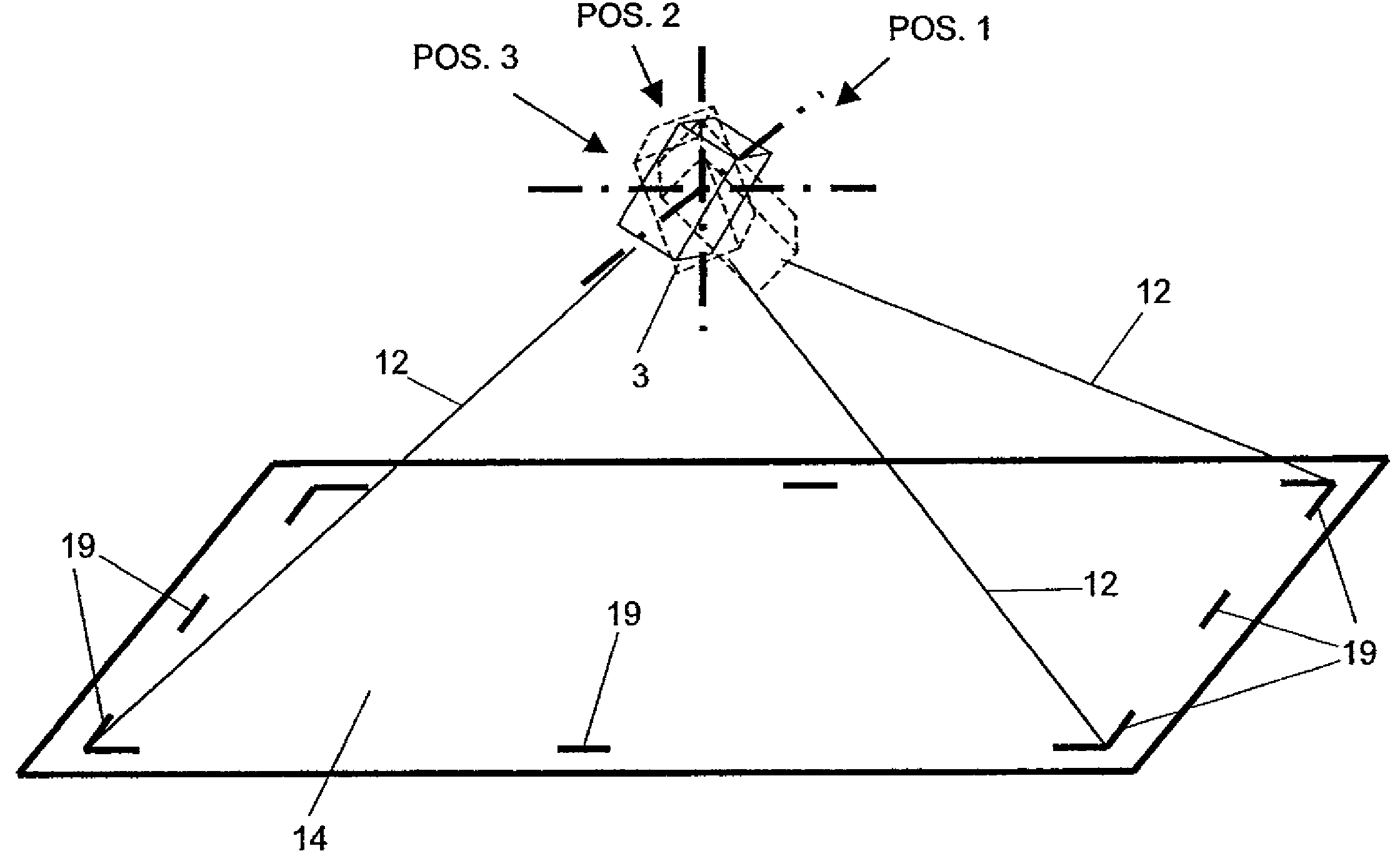
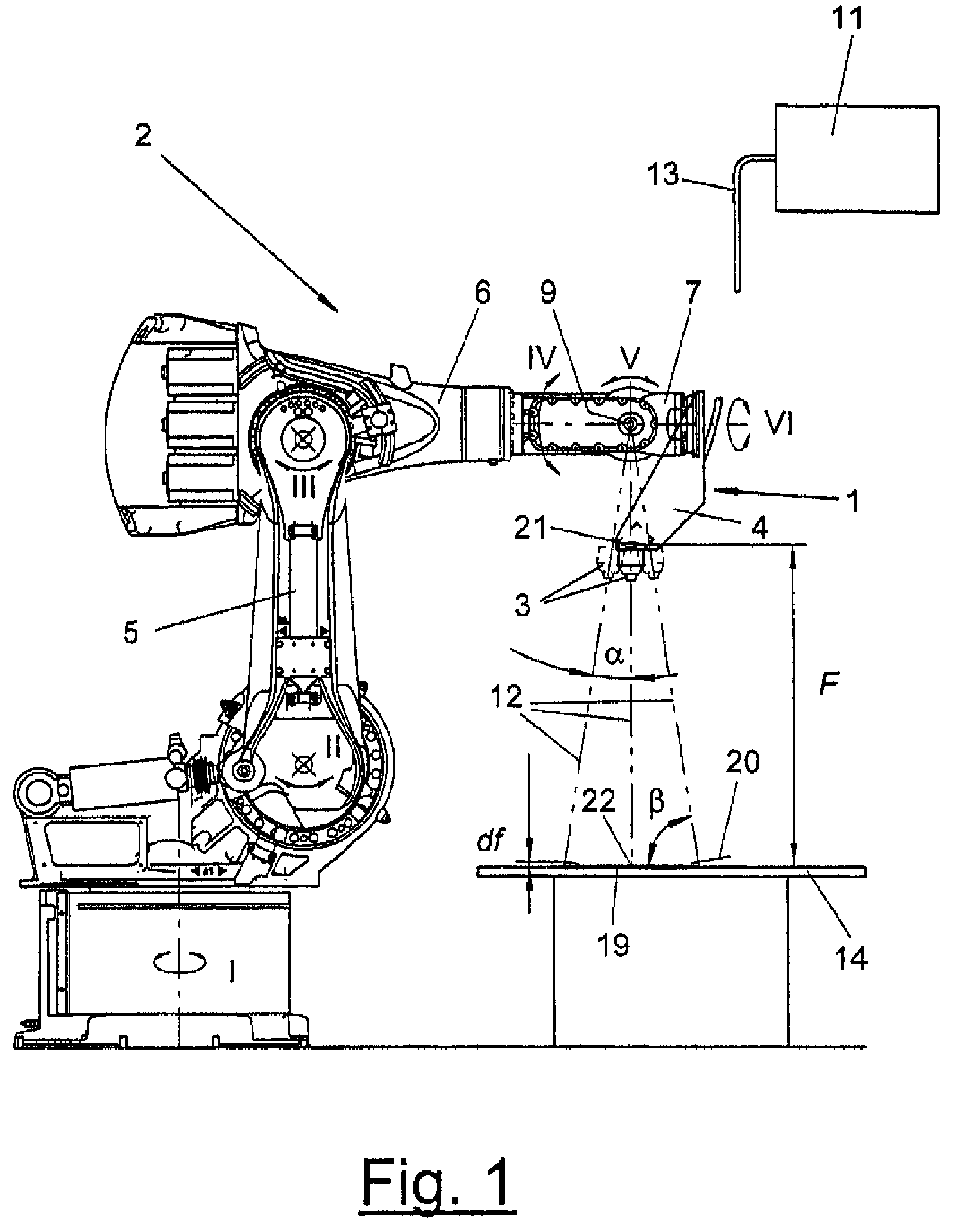
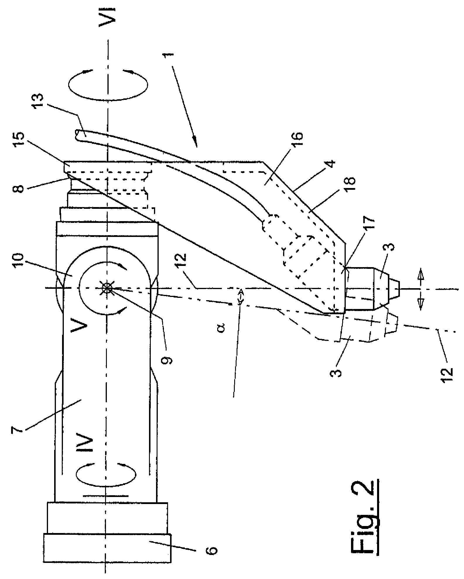
[0023]Referring to the drawings in particular, the present invention pertains to a process for laser machining, especially laser beam welding, of components (14), which may be of any number, type and size. In the preferred embodiment, they are body parts of vehicles and optionally also complete body shells.

[0024]The present invention pertains, furthermore, to a laser welding device (1) or a laser welding station (2) equipped therewith for joining components (14) by means of laser beam welding. It may be, e.g., a geo station or framing station within a manufacturing plant for manufacturing body shells, in which body parts, e.g., a floor part or side panels, etc., are brought into the geometrically correct position in relation to one another, are clamped in this position and joined by means of one or more laser weld seams (19). The laser welding station (2) may be, in addition, a component preparation station, in which, e.g., a side panel group is built up consecutively from a plurali...


PUM

PropertyMeasurementUnit
focal lengthaaaaaaaaaa
lengthaaaaaaaaaa
focal lengthaaaaaaaaaa

Abstract

A method for laser beam machining, in particular laser beam welding of bodywork components (14), with the aid of a remote laser head (3). The laser head is guided by a robot (5) including a multi-axial robot hand (7). During the welding process, the emitted laser beam (12) is guided along the welding path (19) on the component (14) by orientation modifications and with a variable irradiation angle beta. said orientation modifications only being produced by pivoting displacements (7) of the manipulator hand (7) about at least one of its hand axes IV, V, VI.

Description

CROSS REFERENCE TO RELATED APPLICATIONS[0001]This application is a United States National Phase application of International Application PCT / EP2004 / 010603 filed Sep. 22, 2004 and claims the benefit of priority under 35 U.S.C. §119 of German Patent Application DE 103 44 526.9 filed Sep. 24, 2003, the entire contents of which are incorporated herein by reference.FIELD OF THE INVENTION[0002]The present invention pertains to a process for the laser beam machining, especially laser beam welding and cutting, of components, especially body parts.BACKGROUND OF THE INVENTION[0003]It is known from practice that for laser beam welding, a remote laser head is guided along the path to be welded by means of a multiaxial manipulator, without touching the component. The manipulator has a plurality of basic axes and a hand with a plurality of hand axes. The irradiation angle β on the component is maintained extensively constant. This is achieved by a simultaneous and superimposing motion of all mani...

Claims


Application Information

Patent Timeline
Patent Type & Authority Patents(United States)
IPC IPC(8): B23K26/10B23K26/08
CPCB23K26/0884G05B2219/40416
Inventor RIPPL, PETERENGLHARD, ANTONEBERL, MARTIN
Owner KUKA SYSTEMS
Why Eureka
Try Eureka