Method of estimating joint moment of two-legged walking mobile body

a mobile body and joint moment technology, applied in the direction of electric programme control, instruments, program control, etc., can solve the problems of inhibiting the improvement of joint moment estimation accuracy, and the difficulty of grasping the tilt angle of a predetermined region of the two-legged walking mobile body in the absolute coordinate system with a high degree of accuracy, so as to increase the estimation accuracy of the joint moment. , the effect of increasing the estimation accuracy

Inactive Publication Date: 2010-04-13
HONDA MOTOR CO LTD
View PDF20 Cites 10 Cited by
  • Summary
  • Abstract
  • Description
  • Claims
  • Application Information

AI Technical Summary

Benefits of technology

[0011]As stated hereinabove, according to the present invention, the joint moments of the legs can be estimated by using the values of the motion states of the rigid elements in the body coordinate system or the rigid equivalent parts of the two-legged walking mobile body corresponding to the rigid elements, thereby enabling a reduction in arithmetic processing using the tilt information of the two-legged walking mobile body (information on a degree of tilt relative to the vertical direction or the horizontal direction of a certain region of the two-legged walking mobile body). As a result, the estimation accuracy of the joint moments of the legs can be enhanced.
[0013]In this invention, the acceleration sensor can be attached basically to any rigid equivalent part of the two-legged walking mobile body, though it is preferably attached to the rigid equivalent part of the two-legged walking mobile body corresponding to the rigid element to which the body coordinate system is fixed (a second invention). More specifically, if the acceleration sensor is attached to a region other than the rigid equivalent part of the two-legged walking mobile body corresponding to the rigid element to which the body coordinate system is fixed, there is a need to calculate an acceleration vector of the rigid equivalent part corresponding to the rigid element to which the body coordinate system is fixed by using a displacement or the like of the joint of the two-legged walking mobile body from the acceleration vector of the attached region. On the other hand, if the acceleration sensor is attached to the rigid equivalent part corresponding to the rigid element to which the body coordinate system is fixed like the second invention, the positional relationship between the origin of the body coordinate system and the acceleration sensor is fixed and thus the value in the body coordinate system of the acceleration vector of the origin of the body coordinate system can be grasped from the output of the acceleration sensor without using the displacement of the joint of the two-legged walking mobile body. This enables an enhancement of the accuracy of the grasped value in the body coordinate system of the acceleration vector of the origin of the body coordinate system.
[0014]Moreover, in the second invention, the rigid element to which the body coordinate system is fixed is preferably a rigid element connecting a pair of joint elements corresponding to a pair of hip joints of the two-legged walking mobile body (a third invention). More specifically, the rigid element connecting the pair of joint elements corresponding to the pair of hip joints of the two-legged walking mobile body corresponds to the waist of the two-legged walking mobile body and the waist relatively less moves during walking of the two-legged walking mobile body in general. Accordingly, the output of the acceleration sensor can be relatively stabilized by reducing abrupt changes in the outputs of the acceleration sensor and it further enables an enhancement of the accuracy of the grasped value in the body coordinate system of the acceleration vector of the origin of the body coordinate system.
[0021]When estimating the position vector of the point of application of the floor reaction force in this manner, there is a need to grasp the tilt angle to the vertical direction of the rigid equivalent part of the two-legged walking mobile body corresponding to the rigid element to which the body coordinate system is fixed by using a sensor for detecting tilt angles (an angular velocity sensor or a tiltmeter). In this invention, however, the tilt angle may be used only for estimating the point of application of the floor reaction force vector, thus reducing the arithmetic operations using the tilt angle to the minimum. Therefore, even if the tilt angle has an error, the accumulation of arithmetic errors can be held to the minimum, thus securing a sufficiently high accuracy in estimating a joint moment. Moreover, the pressure distribution sensor need not be disposed at the bottom of the foot apt to receive a relatively large load instantaneously, which leads to an advantage in durability of the apparatus configuration for estimating joint moments.
[0028]According thereto, in the state where only the toe-side portion of the foot of the landing leg is determined to be in contact with the ground, the position located the vertical distance between the ankle joint and the metatarsophalangeal joint apart from the vertical position of the ankle joint of the leg downward in the vertical direction is estimated as the vertical position of the point of application of the floor reaction force vector. As a result, the estimation accuracy can be increased in the vertical position of the point of application of the floor reaction force vector.
[0029]In the inventions described hereinabove, the value of the floor reaction force vector and the value of the position vector of the point of application of the floor reaction force vector respectively grasped in the third step and the fourth step are preferably three-dimensional values (a ninth invention). According thereto, the value of the floor reaction force vector and the value of the position vector of the point of application of the floor reaction force vector are grasped according to spatial behaviors of the two-legged walking mobile body, thereby increasing the estimation accuracy of the joint moments estimated based on them.

Problems solved by technology

In all of these methods, however, accumulated errors involved in an integral of detected values of the gyro sensor or an inertial acceleration during the motion of the two-legged walking mobile body often inhibits a measurement of a tilt angle relative to the vertical direction with a fully satisfactory degree of accuracy in general.
Therefore, it is generally hard to grasp the tilt angle of a predetermined region of the two-legged walking mobile body in the absolute coordinate system with a high degree of accuracy.
Therefore, in the method of the patent document 1 requiring a lot of arithmetic processing such as coordinate transformation using the tilt angle as described above, arithmetic errors are easily accumulated, thus inhibiting an improvement of estimation accuracy of the joint moments.

Method used


Image

  • Method of estimating joint moment of two-legged walking mobile body
  • Method of estimating joint moment of two-legged walking mobile body
  • Method of estimating joint moment of two-legged walking mobile body

Examples


Embodiment Construction

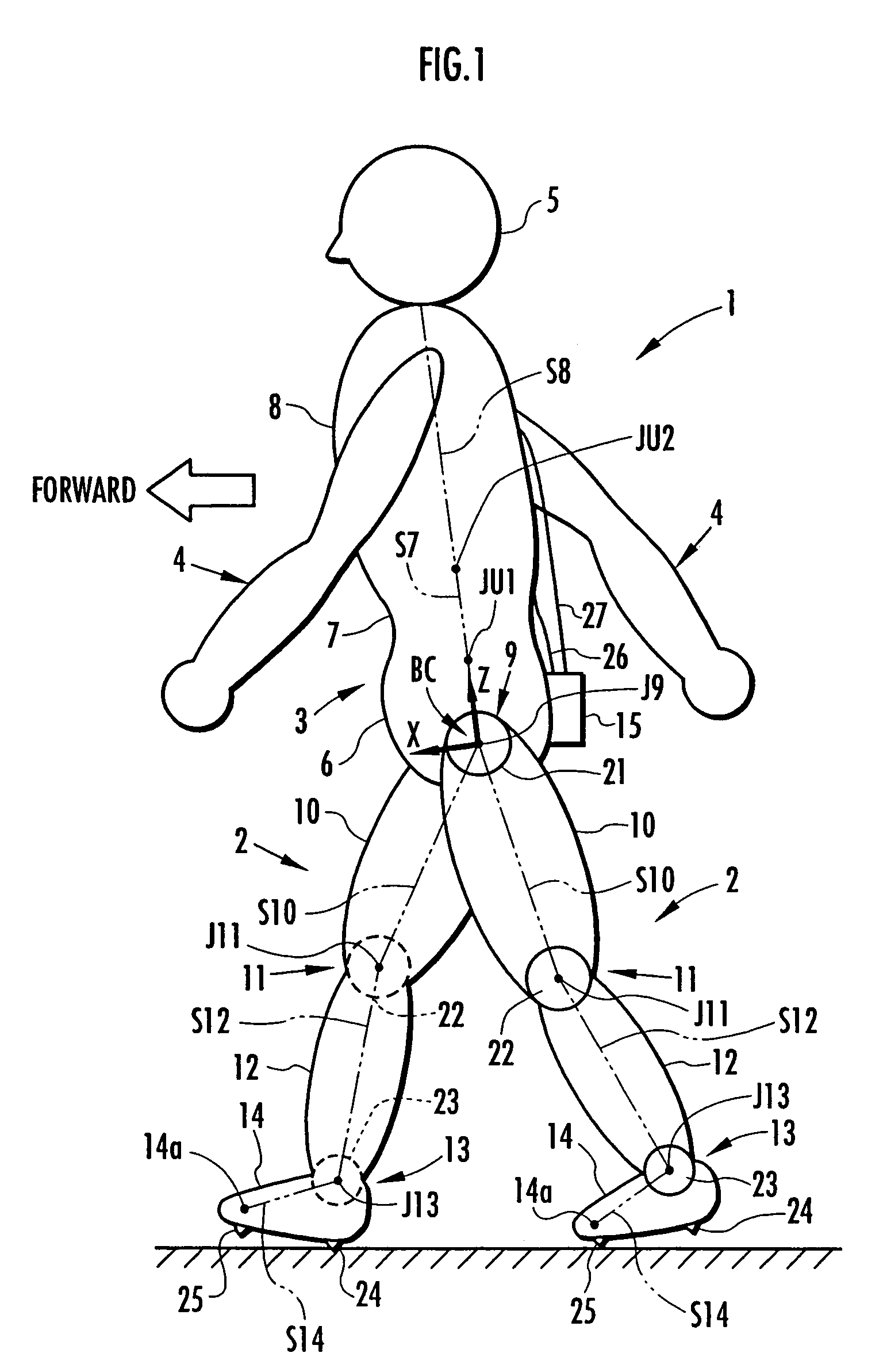
[0040]A preferred embodiment of the present invention will now be described hereinafter with reference to FIG. 1 to FIG. 10. Referring to FIG. 1, there is typically shown a diagram of a general apparatus configuration in an embodiment to which the present invention is applied to a human being as a two-legged walking mobile body. As shown in FIG. 1, the human being 1 has a structure generally classified into a pair of right and left legs 2, 2, a body 3, a pair of right and left arms 4, 4, and a head 5. The body 3 is composed of a waist 6, an abdomen 7, and a chest 8. The waist 6 is coupled to the legs 2, 2 via a pair of right and left hip joints 9, 9 so as to be supported on the both legs 2, 2. Moreover, the arms 4, 4 are extended from the right and left sides of the chest 8 of the body 3 and the head 5 is supported on the upper end of the chest 8. The each leg 2 has a thigh 10 extending from the hip joint 9, a crus 12 extending from the end of the thigh 10 via a knee joint 11, and a...


PUM


Abstract

Displacements of respective joints corresponding to respective joint elements (J9 and the like) of a rigid link model (S1) representing a two-legged walking mobile body (1) are sequentially grasped. Also at the same time, values, in a body coordinate system (BC), of an acceleration vector of the origin of the body coordinate system (BC) fixed to a waist (6) as a rigid element, a floor reaction force vector acting on each leg (2), and a position vector of the point of application of the floor reaction force vector are sequentially grasped. With the use of the grasped values, joint moments respectively generated in an ankle joint (13), a knee joint (14), and a hip joint (9) of each leg (2) are sequentially estimated based on an inverse dynamics model using the body coordinate system. The estimation accuracy of the joint moments of the leg can be enhanced by reducing arithmetic processing using tilt information of the two-legged walking mobile body relative to the gravity direction as much as possible.

Description

FIELD OF THE INVENTION[0001]The present invention relates to a method of estimating moments (joint moments) acting on respective joints of each leg of a two-legged walking mobile body such as a human being or a two-legged walking robot.BACKGROUND ART[0002]When controlling the operation of a walking assist device to assist a human being in making a walking motion, for example, it is necessary to grasp joint moments actually acting on the joints of the legs of the human being. The grasp of the joint moments enables an appropriate determination of a target support force of the walking assist device. Also in a two-legged walking robot, there is sometimes a need to grasp the joint moments actually acting on the joints of the legs appropriately to control its operation.[0003]Accordingly, the applicant of the present application has earlier suggested a method of estimating joint moments of the legs of a two-legged walking mobile body such as a human being in Japanese Patent Laid-Open No. 2...

Claims


Application Information

Patent Timeline
Patent Type & Authority Patents(United States)
IPC IPC(8): G06F19/00B62D57/032
CPCB62D57/032
Inventor KAWAI, MASAKAZUIKEUCHI, YASUSHI
Owner HONDA MOTOR CO LTD
Why Eureka
Try Eureka