Run-in coating for gas turbines and method for producing same

a gas turbine and run-in coating technology, which is applied in the direction of coatings, motors, applications, etc., can solve the problems of undesired gap enlargement and difficult maintenance of the rotating rotor blades from the stationary housing of the compressor, and achieve the effect of less porous and promoting adhesion

Inactive Publication Date: 2010-04-20
MTU AERO ENGINES GMBH
View PDF12 Cites 5 Cited by
  • Summary
  • Abstract
  • Description
  • Claims
  • Application Information

AI Technical Summary

Benefits of technology

[0007]The run-in coating made of the titanium-aluminum material may have a stepped or graded material composition and / or porosity. The run-in coating may be arranged to be less porous, at an inner region arranged directly adjacent to the housing and at an outer region arranged directly adjacent to the rotor blades, than between these two regions. Therefore, the run-in coating may be arranged to be denser and harder at the inner region arranged directly adjacent to the housing, and at the outer region arranged directly adjacent to the rotor blades. The inner region arranged directly adjacent to the housing may be used, in this context, to promote adhesion. The outer region arranged directly adjacent to the rotor blades is used to make available erosion protection.

Problems solved by technology

In aircraft engines, a particular problem is keeping a minimum gap between the rotating rotor blades and the stationary housing of a high pressure compressor.
The highest absolute temperatures and temperature gradients occur in high pressure compressors, and this makes maintaining the gap of the rotating rotor blades from the stationary housing of the compressor more difficult.
Since, on account of the frictional contact of the tips of the rotating rotor blades to the housing, material is eroded, it is possible for an undesired gap enlargement to set in over the entire circumference of housing and rotor.

Method used


Image

  • Run-in coating for gas turbines and method for producing same
  • Run-in coating for gas turbines and method for producing same

Examples


Embodiment Construction

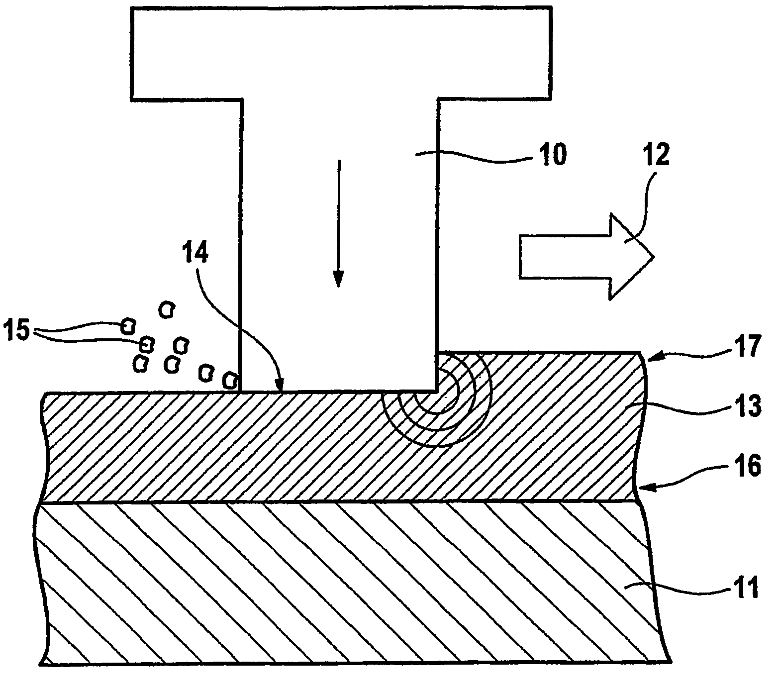
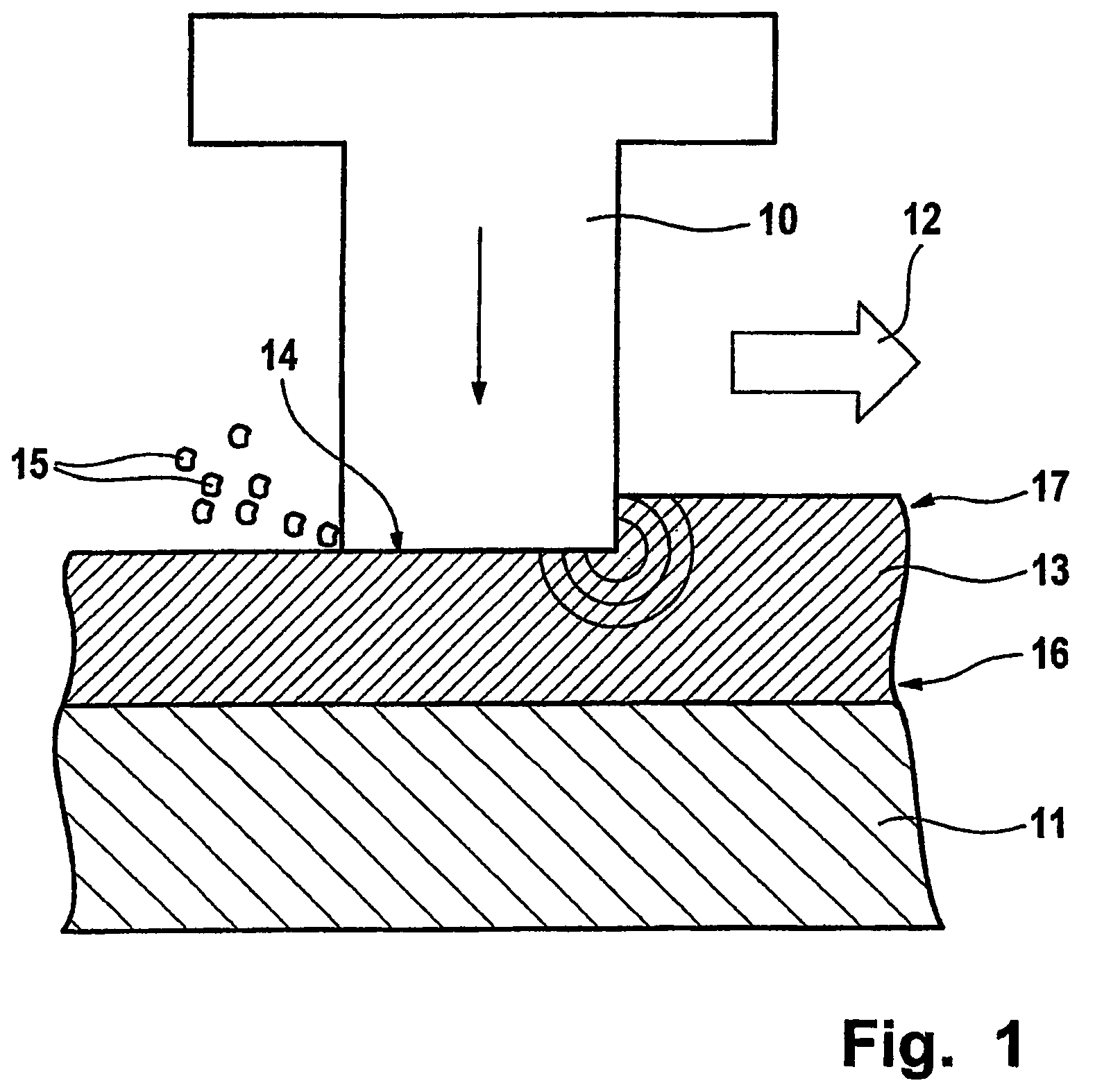
[0010]In a greatly schematic manner, FIG. 1 illustrates a rotating rotor blade 10 of a gas turbine, which rotates with respect to a stationary housing 11 in the direction of arrow 12. A run-in coating is arranged on housing 11. Run-in coating 13 is used to seal a radial gap between a tip or an end 14 of rotating rotor blade 10 and stationary housing 11. The demands made on such a run-in coating are very complex. Thus, for instance, the run-in coating may have to have optimized abrasive characteristics, that is, good chip formation and removability of the abraded material may need to be ensured. Furthermore, there may need to be not be any material transfer to rotating rotor blade 10. Run-in coating 13 may also need to have low frictional resistance. Moreover, run-in coating 13 may need to not ignite when rotating rotor blade 10 brushes against it. Additional demands made on run-in coating 13 may include erosion resistance, temperature stability, resistance to heat change, corrosion ...


PUM

PropertyMeasurementUnit
porosityaaaaaaaaaa
densityaaaaaaaaaa
hardnessaaaaaaaaaa

Abstract

A run-in coating is for gas turbines. The run-in coating is used for sealing a radial gap between a housing of the gas turbine and rotating rotor blades of same, the run-in coating being applied onto the housing. The run-in coating is made of an intermetallic titanium-aluminum material.

Description

FIELD OF THE INVENTION[0001]The present invention relates to a run-in coating for gas turbines and to a method for producing a run-in coating.BACKGROUND INFORMATION[0002]Gas turbines, such as, for example, aircraft engines, include, as a rule, a plurality of rotating rotor blades as well as a plurality of stationary stator blades, the rotor blades rotating together with a rotor, and the rotor blades as well as the stator blades being enclosed by a stationary housing of the gas turbine. It may be provided to optimize all components and subsystems when it comes to improving the performance of an aircraft engine. Among those are also the so-called sealing systems in aircraft engines. In aircraft engines, a particular problem is keeping a minimum gap between the rotating rotor blades and the stationary housing of a high pressure compressor. The highest absolute temperatures and temperature gradients occur in high pressure compressors, and this makes maintaining the gap of the rotating r...

Claims


Application Information

Patent Timeline
Patent Type & Authority Patents(United States)
IPC IPC(8): F01D11/12
CPCF01D11/122Y10T428/12389
Inventor BAYER, ERWINSMARSLY, WILFRIED
Owner MTU AERO ENGINES GMBH
Why Eureka
Try Eureka