Piezoelectric actuator

a piezoelectric actuator and actuator technology, applied in piezoelectric/electrostrictive/magnetostrictive devices, piezoelectric/electrostriction/magnetostriction machines, electrical transducers, etc., can solve the problems of difficult to form leaf springs, difficult to arrange the diaphragm at an optimal position, and less suitable techniques for reducing thickness, etc. problems, to achieve the effect of generating large vibration amplitude, reducing the impa

Inactive Publication Date: 2010-04-20
NEC CORP
View PDF21 Cites 6 Cited by
  • Summary
  • Abstract
  • Description
  • Claims
  • Application Information

AI Technical Summary

Benefits of technology

[0013]In view of the foregoing situations, it is an object of the present invention to provide a small and thin piezo-electric actuator which is capable of generating vibration at a large amplitude, is adjustable for resonance frequency, is provided with high reliability, and is applicable to electronic devices, without causing an increase in dimensions.
[0015]In the piezo-electric actuator thus configured, vibration is caused by the constraining effect between the constraint member and the piezo-electric element, and is amplified by the beam members. Then the constraint member vibrates. Specifically, if vibration is induced at a resonance frequency, which is determined by physical properties, shape, number of constraint member, weight of the piezo-electric body, etc., the constraint member is significantly displaced, while deformation of the piezo-electric body, which has a limited capacity of deformation, is restricted. Thus, it is possible to cause the entire piezo-electric body to vibrate relative to the supporting members at a large amplitude. Further, the resonance frequency can be easily controlled by adjusting the physical properties (material), number etc. of the constraint member. Accordingly, the present invention can provide a piezo-electric actuator that is thin and small, is capable of generating large vibration amplitude, is adjustable for resonance frequency without changing outer dimensions, and has high reliability.
[0024]As described above, according to the piezo-electric actuator of the present invention, the entire piezo-electric body vibrates at a large amplitude relative to the supporting members mainly through displacement of the constraint member. Also, the resonance frequency can be easily controlled by adjusting the physical property (material), number etc. of the constraint member. Further, even in case that an electronic device which contains the piezo-electric actuator is dropped, the constraint member, made of an elastic material, can mitigate the impact to the piezo-electric body by absorbing the impact energy. In this way, according to the present invention, a piezo-electric actuator can be provided that is thin and small, is capable of generating large vibration amplitude, is adjustable for resonance frequency without changing outer dimensions, and has high reliability.

Problems solved by technology

Therefore, this technique is less suitable for a reduction in thickness.
Further, since springs and a diaphragm are inserted in the housing according to the configuration in this patent document, it is very difficult to arrange the diaphragm at an optimal position.
On the other hand, in the technique disclosed in the specification of Japanese Patent Laid-open Publication No. 2001-17917, it is necessary that a circular base is combined with circular piezo-electric ceramic or rectangular piezo-electric ceramic, because it is difficult to form leaf springs if the base is substantially not circular.
In the former case, since the piezo-electric ceramic has to be machined into a circular shape, the fabrication steps and the cost will increase because of machining the ceramic into a circular shape, and because forming the larger extra portion in advance worsens yield rate, etc.
On the other hand, in the latter case, since the piezo-electric ceramic cannot be arranged on the peripheral region of the base in an effective fashion, vibration does not transmit efficiently to the base, making it difficult to obtain sufficient vibration displacement.
This causes distortion in sound when a vibratory film is attached for use as an acoustic element.

Method used


Image

  • Piezoelectric actuator
  • Piezoelectric actuator
  • Piezoelectric actuator

Examples


example 1

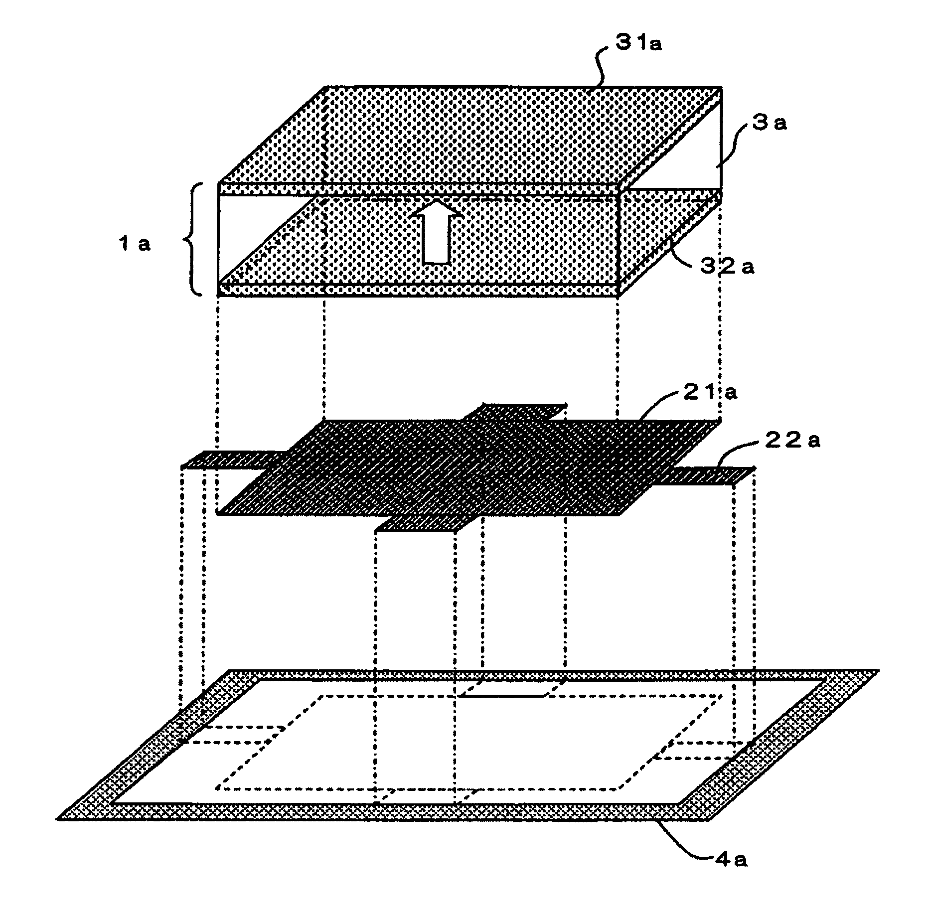
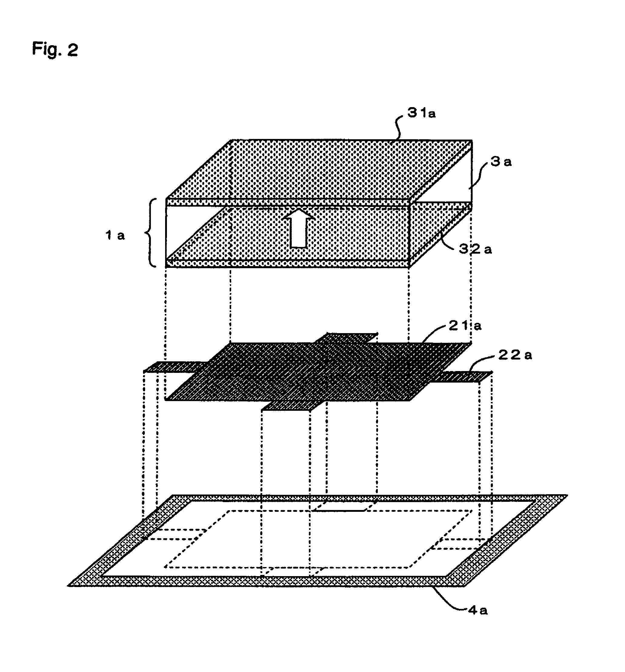
[0092]A piezo-electric actuator illustrated in FIGS. 12A, 12B was fabricated. FIG. 12A illustrates a top plan view of a base, beam members, and a supporting member. Values in the figure are in units of millimeters. FIG. 12B in turn illustrates an exploded perspective view of the piezo-electric element. The piezo-electric actuator of Example 1 has piezo-electric element 101a, base 121a, supporting member 104a, and beam members 122a. Piezo-electric element 101a is bonded to base 121a with epoxy-based adhesive, while base 121a is connected to supporting member 104a via four beam members 122a.

[0093]As illustrated in FIG. 12B, piezo-electric element 101a is a single-layer type piezo-electric element consisting of upper insulating layer 133a, upper electrode layer 131a, piezo-electric body 103a, lower electrode layer 132a, and lower insulating layer 133a′. Upper insulating layer 133a and lower insulating layer 133a′ have a length of 10 mm, a width of 10 mm, and a thickness of 50 μm. Piez...

example 2

[0100]The piezo-electric actuator of Example 2 has base 121b, supporting member 104b, and beam members 122b. In Example 2, the number of beam members 122b attached to the base was changed from four in Example 1 to two in order to confirm the degree of reduction in the resonance frequency. As illustrated in FIG. 14, conditions were the same as in Example 1 except for the number of beam members 122b. The piezo-electric actuator had a circular form having a diameter of 16 mm and a thickness of 0.45 mm. Values in the figure are in units of millimeters. The piezo-electric actuator provided a reciprocal vibration mode, with a resonance frequency of 498 HZ, a maximum amplitude of the vibration velocity of 172 mm / s, and a maximum vibration velocity ratio of 0.86.

[0101]It was confirmed from the comparison between Examples 1 and 2, that the resonance frequency can be lowered by changing the number of beam members without causing a large change in the vibration mode or in the vibration velocit...

example 3

[0102]In Example 3, the configuration of Example 2 was used, while the material of the base was changed from phosphor bronze to SUS304. The other conditions are the same as in Example 2. The piezo-electric actuator provided a reciprocal vibration mode, with a resonance frequency of 572 HZ, and a maximum amplitude of the vibration velocity of 189 mm / s.

[0103]It was confirmed from the comparison between Examples 2 and 3, that the resonance frequency can be adjusted by changing the material of the base without causing a large change in the shape, vibration mode, and maximum amplitude of the vibration velocity of the actuator.


PUM


Abstract

A piezo-electric actuator comprising: piezo-electric element 1a having piezo-electric body 3a which is provided with at least two opposing surfaces, wherein the surfaces perform an expanding and contracting motion in accordance with the state of an electric field; a constraint member 21a for constraining piezo-electric element 1a on at least one of the two surfaces, a supporting member disposed around constraint member 21a, and a plurality of beam members 22a each having both ends fixed to constraint member 21a and supporting member 4a, respectively, wherein each beam member has a neutral axis for bending in a direction substantially parallel with the constrained surface, wherein the constraint member vibrates by vibration which is generated by the constraining effect between the constraint member and the piezo-electric element, and is amplified by the beam members.

Description

TECHNICAL FIELD[0001]The present invention relates to a small-size piezo-electric actuator which is used in electronic devices.BACKGROUND ART[0002]Electromagnetic actuators have been generally utilized as driver components for acoustic elements such as speakers, due to their easy handling. An electromagnetic actuator comprises a permanent magnet, a voice coil, and a diaphragm, and causes a low-stiffness diaphragm that is made of an organic film and is fixed to the coil to vibrate, through the operation of a magnetic circuit in a stator which uses the magnet. Therefore, they present a reciprocal vibration mode and can provide large vibration amplitude.[0003]By the way, the demand for power-saving actuators has been increasing, together with an increased demand for cellular phones and personal computers in recent years. However, electromagnetic actuators have the problem that the reduction in power consumption is difficult due to the large amount of current which flows in the voice co...

Claims


Application Information

Patent Timeline
Patent Type & Authority Patents(United States)
IPC IPC(8): H01L41/053H02N2/04H04R17/00
CPCH04R17/00
Inventor ONISHI, YASUHARUSASAKI, YASUHIROTOKI, NOZOMI
Owner NEC CORP
Why Eureka
Try Eureka