Crash sensing via piezoelectric sensors

a piezoelectric sensor and sensor technology, applied in the field of piezoelectric sensors, can solve the problems of reducing reliability, severe delay in the response time of the central accelerometer, and reducing reliability, so as to reduce the impact

Active Publication Date: 2010-04-20
METHODE ELETRONICS INC
View PDF18 Cites 3 Cited by
  • Summary
  • Abstract
  • Description
  • Claims
  • Application Information

AI Technical Summary

Benefits of technology

[0021]The method also could be used to apply cushioning to reduce the impact from a hard landing by an airborne object, helicopter, or plane.

Problems solved by technology

The delayed response time of a central accelerometer is a severe constraint for inflatable occupant restraints (airbags), as the occupant may
have moved into the deployment space leading to injuries from the rapidly expanding device.
The delay is particularly serious for side impact sensing, due to the limited space between the occupant and the door impact point.
The delayed response time of accelerometers has led others to propose installing sensors close to the point of impact, namely in front of the engine or on the door, but with the adverse consequences of reduced reliability, greater expense, and unneeded system complexity.
Sensors located close to the point of impact often are destroyed by the impact, thus cutting off critical information.
Locating crash sensors close to the point of impact has the effect of subjecting the sensors to environmental extremes, leading to possible failure.
Accelerometers subjected to extreme heat and cold may need to be recalibrated as they age, causing inconvenience and expense to the owner and producer.
Furthermore, since the vehicle designer does not know in advance exactly where an impact might occur, many sensors are required to cover all the possible impact locations.
This sensor proliferation leads to reduced system reliability and greater expense, due to additional wiring, connectors, and attachment of the sensors.
Further constraints are caused by the axial sensitivity of accelerometers, which require precise alignment with the vehicle axes.
There is a need to locate the accelerometers at specific points in the vehicle; otherwise the desired sensitivity is compromised.
The PVDF sensors are thin (less than 25 μm). unobtrusive, self-powered, adaptable to complex contours, and available in a variety of configurations.
However, current technologies with airbag deployment in both the front and sides of the vehicle, in addition to two-stage airbag deployment, has rendered these algorithms too slow for adequate airbag deployment.
Because PVDF sensors possess very high bandwidth, they record vibrations or acoustic waves at frequencies not possible with accelerometers.
Thus, an unaddressed need exists in the industry to address the aforementioned deficiencies and inadequacies to analyze the input from multiple piezoelectric sensors which are located on the windshield of a vehicle.

Method used


Image

  • Crash sensing via piezoelectric sensors
  • Crash sensing via piezoelectric sensors
  • Crash sensing via piezoelectric sensors

Examples


Embodiment Construction

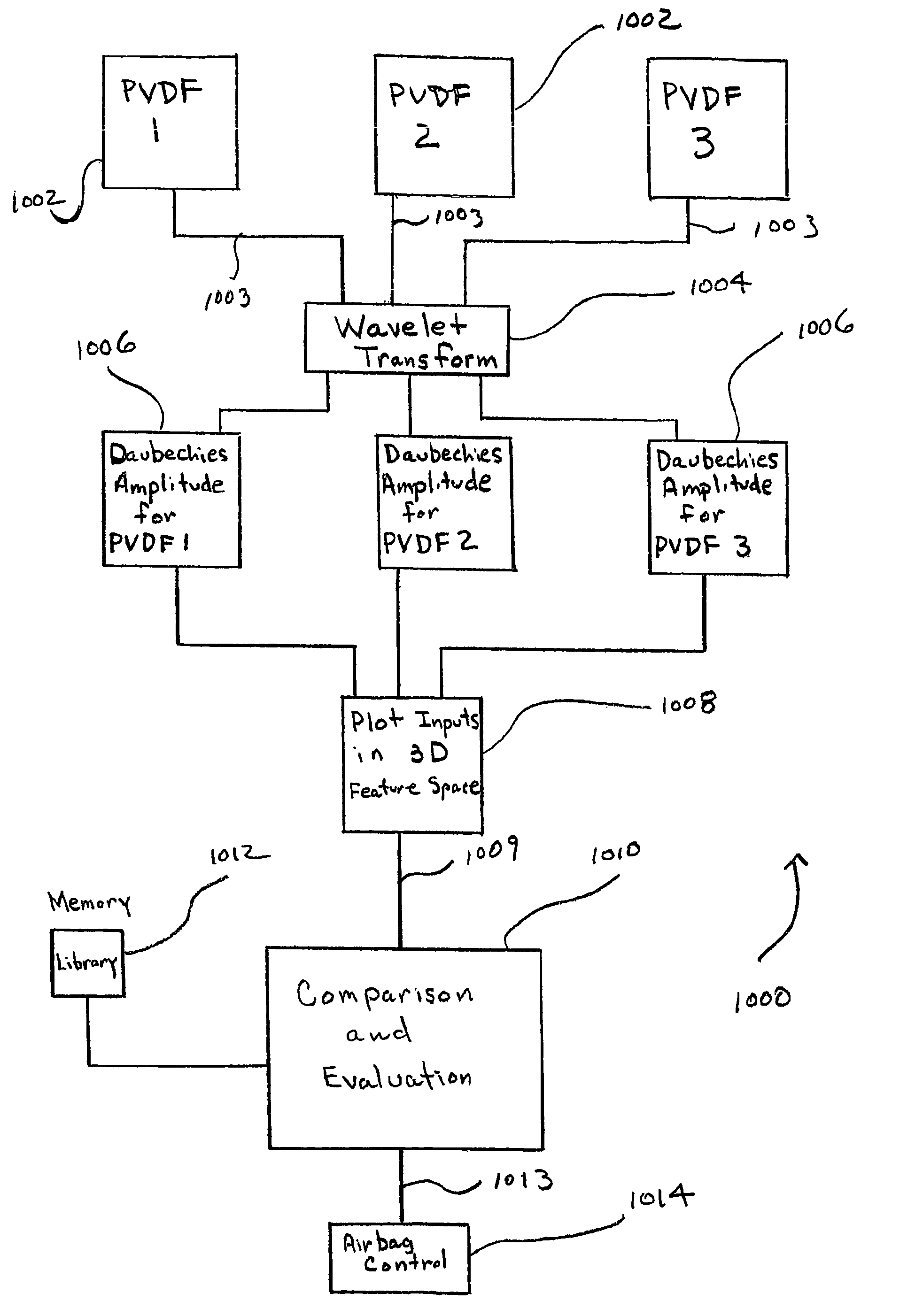
[0038]FIG. 9 depicts a flow diagram of a preferred embodiment of the present invention.

[0039]The method 1000 includes providing three PVDF piezoelectric sensors 1002 mounted on the inside surface of a vehicle windshield (see FIG. 9). A sample of a single response 1003 over a predetermined period of time from each piezoelectric sensor 1002 is obtained. An application-specific integrated circuit (not shown) may be utilized to control sampling of the piezoelectric sensors 1002.

[0040]The responses 1003 from the three piezoelectric sensors 1002 are subjected to wavelet analysis via a Daubechies wavelet analysis 1004. The Daubechies wavelet analysis 1004 employs a Daubechies transfer function that performs signal conditioning on the single responses 1003 to produce Daubechies amplitudes 1006 for each piezoelectric sensor 1002.

[0041]The Daubechies amplitudes 1006 are aggregated and the intersection (commonality point) 1109 of the aggregated Daubechies amplitudes 1006 is plotted 1008 in thr...


PUM


Abstract

A system and method for characterizing piezoelectric sensor responses for automotive vehicle crash analysis, is disclosed. The method employs Daubechies wavelet analysis (1006) to plot signal response amplitudes (1008) in three-dimensional space of at least one piezoelectric sensor. A cluster, signifying a combination of Daubechies amplitudes of the at least one piezoelectric sensor in three-dimensional space, is compared to reference clusters (1010) stored in the automotive vehicle. Based on results from comparing the cluster to the reference clusters, instructions are transmitted to an occupant restraint control system (1013) in the vehicle to deploy a specific airbag at a specific power level.

Description

REFERENCE TO RELATED APPLICATIONS[0001]This application claims priority to U.S. provisional application entitled, “Crash Sensing Via Piezoelectric Sensors”, Ser. No. 60 / 482,695, filed Jun. 25, 2003.FIELD OF THE INVENTION[0002]The present invention is related to piezoelectric sensors and, more particularly, is related to a system and method for characterizing signals detected by multiple piezoelectric sensors applied to an automotive vehicle.BACKGROUND OF THE INVENTION[0003]In a vehicle crash sensing and occupant protection system, multiple sensors may be used to determine the origin of the impact and other useful characteristics of the crash, to optimize the occupant restraining devices. As seen in FIG. 1, the stress waves from a vehicle impact propagate into the windshield glass in less than two milliseconds after impact, whereas the change in acceleration caused by the same impact is delayed by up to 20 milliseconds, as sensed by an accelerometer centrally located in the vehicle. ...

Claims


Application Information

Patent Timeline
Patent Type & Authority Patents(United States)
IPC IPC(8): B60R21/00B60RB60R22/00
CPCB60R21/013B60R21/0136B60R2021/01302
Inventor KITHIL, PHILIP
Owner METHODE ELETRONICS INC
Why Eureka
Try Eureka