Capacitive device

a capacitive device and capacitive technology, applied in the direction of fixed capacitor details, electrochemical generators, fixed capacitors, etc., can solve the problems of reducing the efficiency of electrical contact, and reducing the mechanical stress and strain. , to achieve the effect of minimizing mechanical stress and strain and efficient electrical conta

Inactive Publication Date: 2010-04-27
CORNING INC
View PDF8 Cites 31 Cited by
  • Summary
  • Abstract
  • Description
  • Claims
  • Application Information

AI Technical Summary

Benefits of technology

[0016]Capacitive devices, as described herein, address one or more of the above-mentioned disadvantages of conventional capacitive devices and provide one or more of the following advantages: efficient electrical contact between current collectors, electrical isolation of electrodes, electrochemical stability, while minimizing the mechanical stress and strain applied to the electrodes. The capacitive devices of the present invention are adaptable to a wide range of electrode diameters and electrode stack lengths.

Problems solved by technology

Electrically connecting electrodes to a power source is a challenging aspect for EDLC and CDI applications.
Minimizing the deformations applied to the electrodes is difficult, especially while attempting to maximize the electrical and mechanical integrity of an electrical interconnect to the electrodes.
Brazing or soldering alloys typically will not withstand either the EDLC or the CDI electrochemical environments.
Brazing and / or soldering to carbon is difficult due, in part, to the low strength of activated carbon.
Conductive adhesives formulated using highly conductive metal powders are costly and / or are prone to corrosion.
Conductive adhesives formulated using carbon powders generally have insufficient electrical conductivity for use in a capacitor.
However the resistive losses introduced by conducting charge around the circumference of the electrode in a small diameter wire or thin strip lead degrade performance, and no simple means has been found to use this attachment scheme while incorporating a high efficiency current collector.
Also, the logistics of attaching leads to individual electrodes are not appealing.

Method used


Image

  • Capacitive device
  • Capacitive device
  • Capacitive device

Examples


example 1

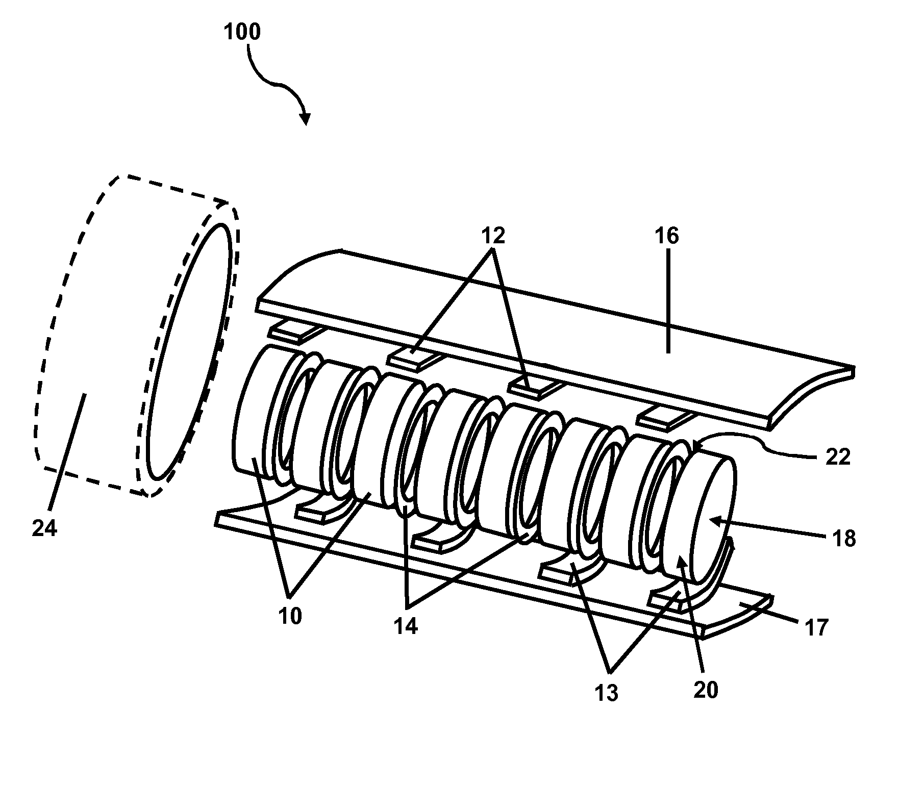
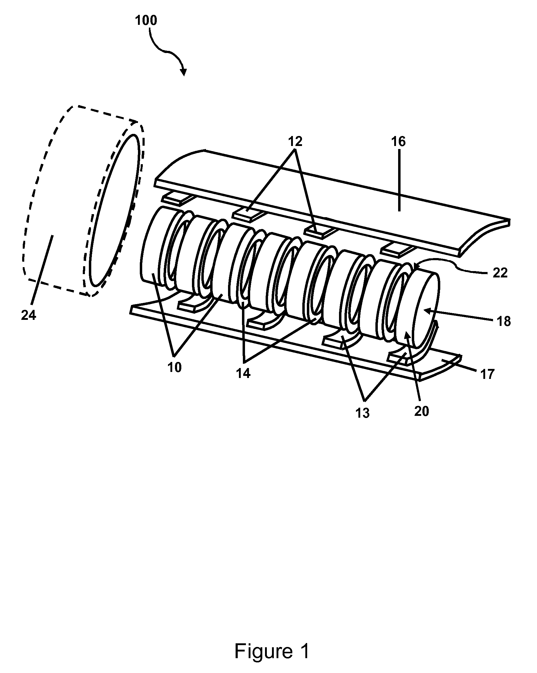
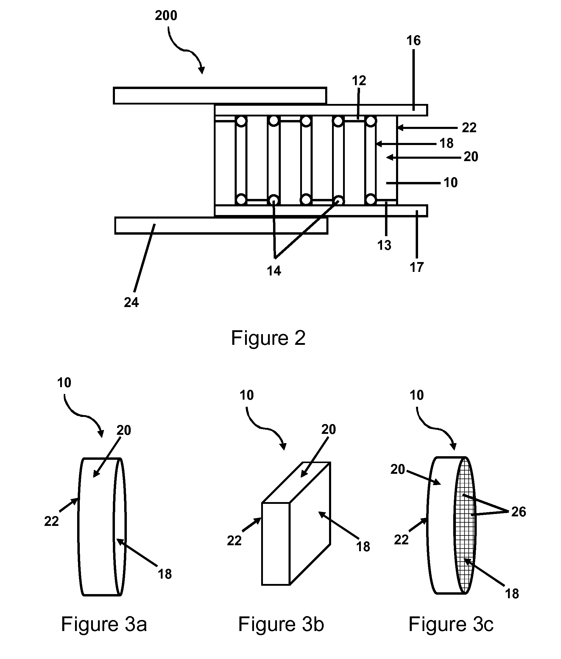
[0052]In this example, the capacitive device comprises a linear stack of carbon honeycomb electrodes, which can be charged with alternating polarity.

[0053]A compliant insulating material is used to manage mechanical stress and provide selective electrical isolation to the electrodes within the linear stack. Two (or more) simple strips of conductive foil are used to provide current collector / bus bar functionality to the electrodes in the linear stack. Through the application of diametrical compressive stress, a good electrical connection is made between the current collectors and electrodes.

[0054]FIG. 5 is a capacitive device, according to one embodiment. A rigid outer housing 24 was used to contain the linear electrode stack comprising honeycomb electrodes and current collector sheets. The outer housing containing concave cylindrical grooves was used to apply distributed mechanical compressive force to the current collector / electrode interfaces.

[0055]Current collectors 16 and 17 wer...


PUM


Abstract

Capacitive devices are described having electrical interconnects of electrodes which possess efficient electrical contact between current collectors, electrical isolation of electrodes, and / or electrochemical stability, while minimizing the mechanical stress and strain applied to the electrodes. The capacitive devices are adaptable to a wide range of electrode diameters and electrode stack lengths.

Description

BACKGROUND[0001]1. Field of the Invention[0002]The present invention relates generally to a capacitive device and more particularly to a capacitive device comprising an electrical interconnect useful for electric double layer capacitors and / or for capacitive deionization.[0003]2. Technical Background[0004]Capacitors, like batteries, store energy in the electrical field between a pair of oppositely charged conductive plates. Developed more than 250 years ago, capacitors are frequently used in electrical circuits as energy storage devices. In recent years, new families of capacitive devices have been developed which are based on charge separation of ions in solution and the formation of electrical double layers.[0005]An electric double layer capacitor (EDLC) is an example of a capacitor that typically contains porous carbon electrodes (separated via a porous separator), current collectors and an electrolyte solution. When electric potential is applied to an EDLC cell, ionic current fl...

Claims


Application Information

Patent Timeline
Patent Type & Authority Patents(United States)
IPC IPC(8): H01G9/00
CPCH01G4/232H01G4/005
Inventor BOURCIER, ROY JOSEPH
Owner CORNING INC
Why Eureka
Try Eureka