
Circulation pump for circulating downhole fluids, and characterization apparatus of downhole fluids

a circulation pump and fluid technology, applied in the direction of non-positive displacement fluid engines, survey, borehole/well accessories, etc., can solve the problems of frequent change of sample pressure and temperature, damage or spoilage, and damage to samples, etc., to achieve easy and effective filling and reduce the size of the circulation pump

Inactive Publication Date: 2010-05-04
SCHLUMBERGER TECH CORP
View PDF58 Cites 9 Cited by
  • Summary
  • Abstract
  • Description
  • Claims
  • Application Information

AI Technical Summary

Benefits of technology

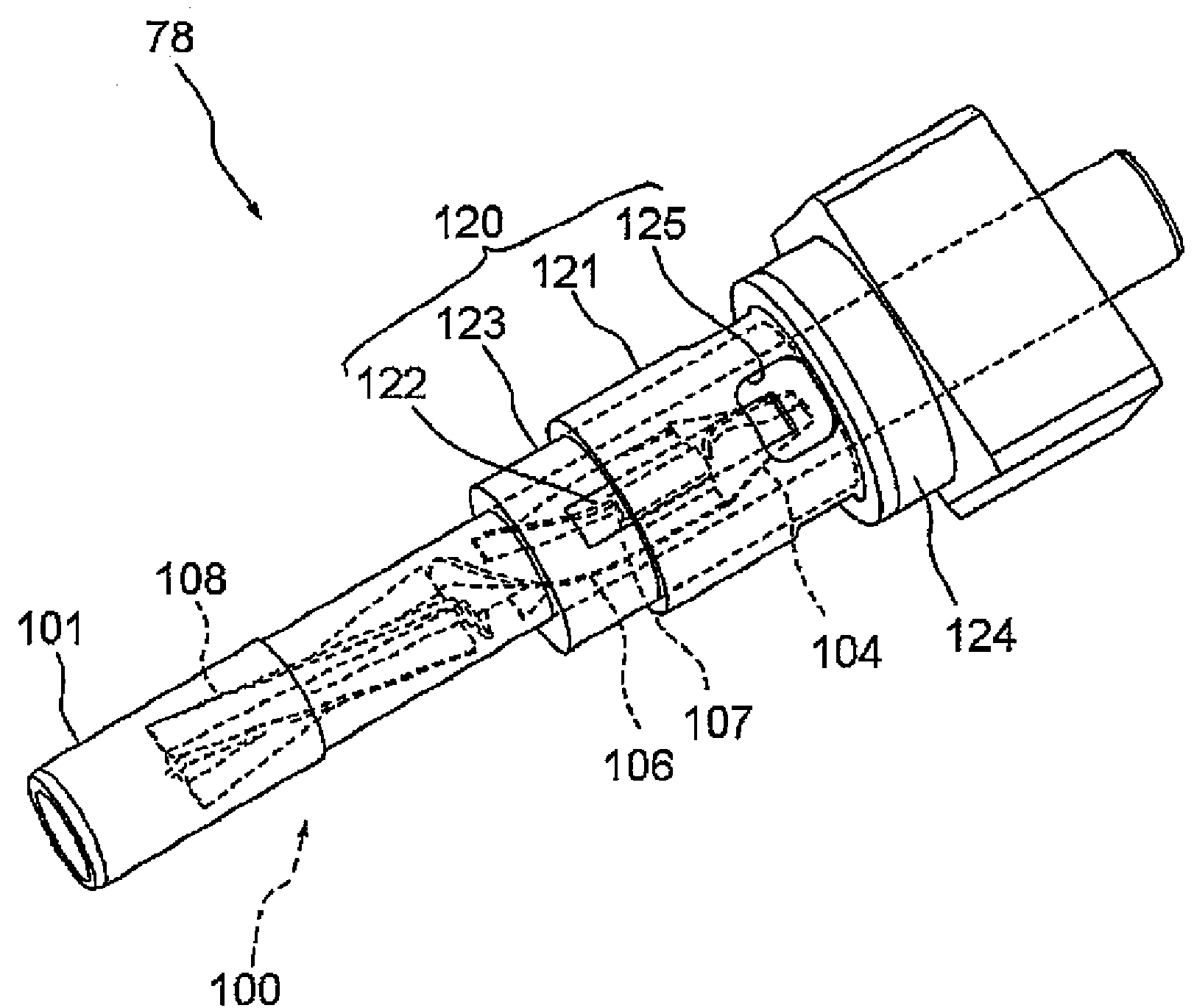
The patent describes methods and apparatus for analyzing downhole fluids by isolating them from the formation and borehole in a flowline of a fluid analysis module. A pressure and volume control unit is integrated with the flowline to determine the characteristics of the isolated fluids. The isolated fluid sample can be circulated in a closed loop line to improve accuracy of phase behavior measurements. A circulation pump is provided to circulate the sample in the loop line. The circulation pump is a small and efficient axis flow type pump that can be easily cleaned and maintained. The invention allows for accurate and reliable analysis of downhole fluids.

Problems solved by technology

In this, samples may be damaged during the transfer from one vessel to another.
Furthermore, sample pressure and temperature frequently change during conveyance of the samples from a wellsite to a remote laboratory despite the techniques used for maintaining the samples at downhole conditions.
The sample transfer and transportation procedures currently in use are known to damage or spoil formation fluid samples by bubble formation, solid precipitation in the sample, among other difficulties associated with the handling of formation fluids for surface analysis of downhole fluid characteristics.
In addition, laboratory analysis at a remote site is time consuming.
This hinders the ability to satisfy users' demand for real-time results and answers (i.e., answer products).
However, a PVCU that is able to operate with precision at high downhole temperature conditions is not currently available.
Conventional apparatuses for changing the volume of fluid samples under downhole conditions use hydraulic pressure with one attendant shortcoming that it is difficult to precisely control the stroke and speed of the piston under the downhole conditions due to oil expansion and viscosity changes that are caused by the extreme downhole temperatures.
Furthermore, oil leakages at O-ring seals are experienced under the high downhole pressures requiring excessive maintenance of the apparatus.
However, this kind of pump has several disadvantages when used for the downhole fluids.
The dead volume of the linear stroke piston type pump is very big, and it requires a dynamic pressure seal on the pistons.
Further, the pump of this type contributes to volume changes in the pumped fluids.
Further, if the pump does not function, it takes a long time to change a first sample of a first measurement point to a second sample of another measurement point by purging the first sample out from the looped flowline.
As a result, two samples are mixed, and measurement error may occur when the purging time is not sufficient.
However, the size of the gear pump is big, and the dead volume is also big because of the size of the gears.
If a small amount of sand is present in the fluid, the sand sticks between the gears and damages them or stops their rotation.
This is not suitable for use in quick pressure change circuits such as bubble point detectors.
This pump has capability of large flow rate, but the pump itself requires dead fluid volume.
As described above, conventionally, there have been problems in finding a proper circulation pump to be used for circulating downhole fluids

Method used


Image

  • Circulation pump for circulating downhole fluids, and characterization apparatus of downhole fluids
  • Circulation pump for circulating downhole fluids, and characterization apparatus of downhole fluids
  • Circulation pump for circulating downhole fluids, and characterization apparatus of downhole fluids

Examples


Embodiment Construction

[0041]Illustrative embodiments and aspects of the invention are described below. In the interest of clarity, not all features of an actual implementation are described in the specification. It will of course be appreciated that in the development of any such actual embodiment, numerous implementation-specific decisions must be made to achieve the developers' specific goals, such as compliance with system-related and business-related constraints, that will vary from one implementation to another. Moreover, it will be appreciated that such development effort might be complex and time-consuming, but would nevertheless be a routine undertaking for those of ordinary skill in the art having benefit of the disclosure herein.

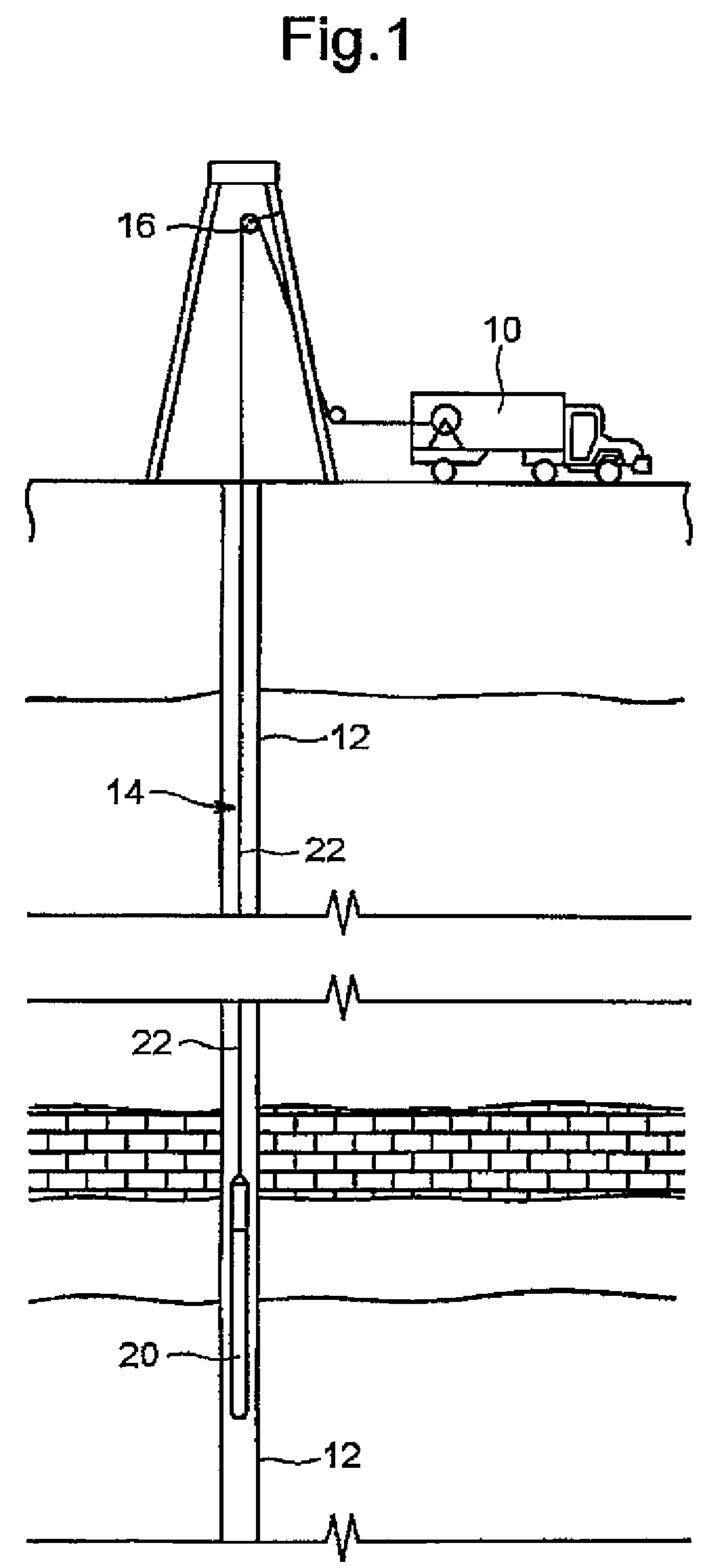
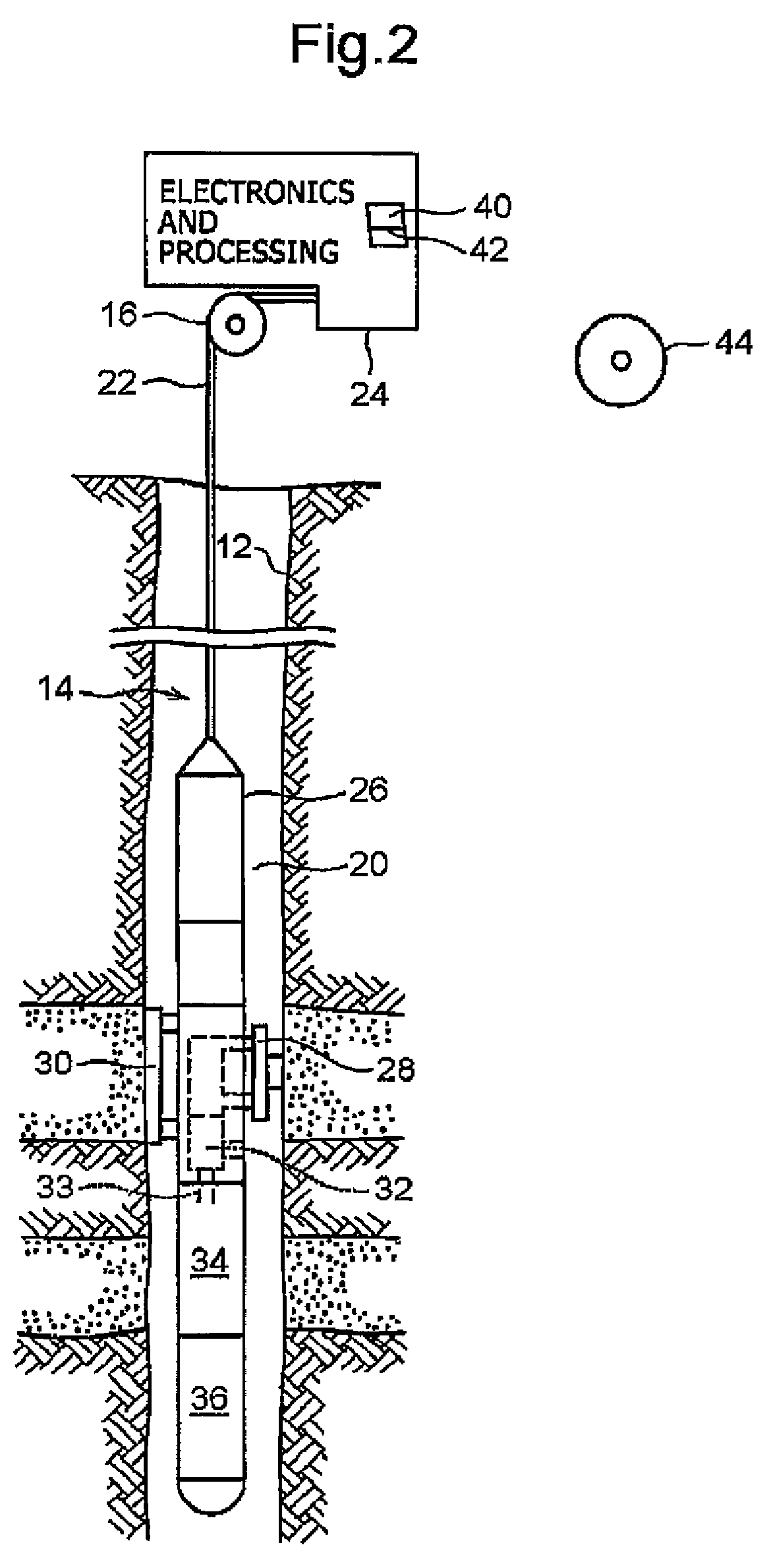
[0042]The present invention is applicable to oilfield exploration and development in areas such as down hole fluid analysis using one or more fluid analysis modules in Schlumberger's Modular Formation Dynamics Tester (MDT), for example.

[0043]FIG. 1 is a schematic repres...


PUM


Abstract

A circulation pump for circulating downhole fluids is provided. The circulation pump includes a cylindrical pump housing, a shaft secured in the pump housing extending in a longitudinal direction thereof, an impeller rotating around the shaft in the pump housing, a cylindrical magnetic coupler rotating around the pump housing, the cylindrical magnetic coupler including a magnet, and a motor positioned outside of the pump housing and connected to the magnetic coupler to rotate the magnetic coupler around the pump housing. The impeller is provided with a magnetic piece, which is capable of being magnetically connected with the magnet of the cylindrical magnetic coupler to cause the impeller to rotate around the shaft by rotating the cylindrical magnetic coupler around the pump housing.

Description

CROSS REFERENCE TO RELATED APPLICATIONS[0001]This application is related to co-pending and commonly owned U.S. patent application Ser. No. 11 / 203,932, filed Aug. 15, 2005, entitled “Methods and Apparatus of Downhole Fluid Analysis”, the entire contents of which are incorporated herein by reference.FIELD OF THE INVENTION[0002]The present invention relates to the field of analysis of downhole fluids of a geological formation for evaluating and testing the formation for purposes of exploration and development of hydrocarbon-producing wells, such as oil or gas wells. More particularly, the present invention is directed to a circulation pump for circulating downhole fluids, and a characterization apparatus of downhole fluids including the circulation pump.BACKGROUND[0003]Downhole fluid analysis is an important and efficient investigative technique typically used to ascertain characteristics and nature of geological formations having hydrocarbon deposits. In this, typical oilfield explora...

Claims


Application Information

Patent Timeline
Patent Type & Authority Patents(United States)
IPC IPC(8): E21B47/08
CPCE21B49/082F04D13/10F04D13/024F04D3/00E21B43/128E21B49/10
Inventor KANAYAMA, KAZUMASAODASHIMA, RYUKIONODERA, SHUNETSUSUGIYAMA, HITOSHIKINJO, HIDEKI
Owner SCHLUMBERGER TECH CORP
Learn More