Bioassay unit and substrate for bioassay

a bioassay and substrate technology, applied in the field of bioinformatics, can solve the problems of unstable operation of the servo control system, uneven presence of detection substance and target substance from the optical viewpoint, complex arrangement of dropper groups, etc., to achieve stable distance between lens and substrate, eliminate noise from servo error signals, and stabilize the effect of servo controlled operation

Inactive Publication Date: 2010-05-04
SONY CORP
View PDF16 Cites 6 Cited by
  • Summary
  • Abstract
  • Description
  • Claims
  • Application Information

AI Technical Summary

Benefits of technology

[0019]This “bioassay substrate” makes it possible to irradiate excitation light from a back side of a detecting section arranged on the substrate and to condense fluorescence, which has been obtained from the detecting section by the irradiation, on the back side of the detecting section to determine the intensity of the fluorescence. Accordingly, a wider space can be obtained above the substrate. As a consequence, a device for dropping a sample solution and a group of devices associated with the dropping device can be arranged with a higher designing tolerance.
[0028]As has been described in the above, the bioassay system according to the present invention has the technical significance that it provides the relevant business field with a technique to solve the problem in allocating spaces for the sample solution dropper and the fluorescence intensity determination unit and, when the substrate is adopted, also with a technique to reduce noises in servo error signals and to permit stabilization of serve-controlled operations (servo control of focusing and servo control of tracking).

Problems solved by technology

If a construction is adopted such that a detection unit is arranged above the substrate for the detection of the intensity of fluorescence emitted from each fluorescence-labeled target substance, a problem therefore arises in the allocation of spaces for the dropper group and the detection unit, leading to a technical problem that the arrangement of the dropper group becomes complex.
On the surface of the substrate, however, the detection substance and the target substance are unevenly present from the optical viewpoint.
As a consequence, the servo error signal includes a large noise, developing a technical problem that the operations of the servo control systems are rendered unstable.

Method used


Image

  • Bioassay unit and substrate for bioassay
  • Bioassay unit and substrate for bioassay
  • Bioassay unit and substrate for bioassay

Examples


Embodiment Construction

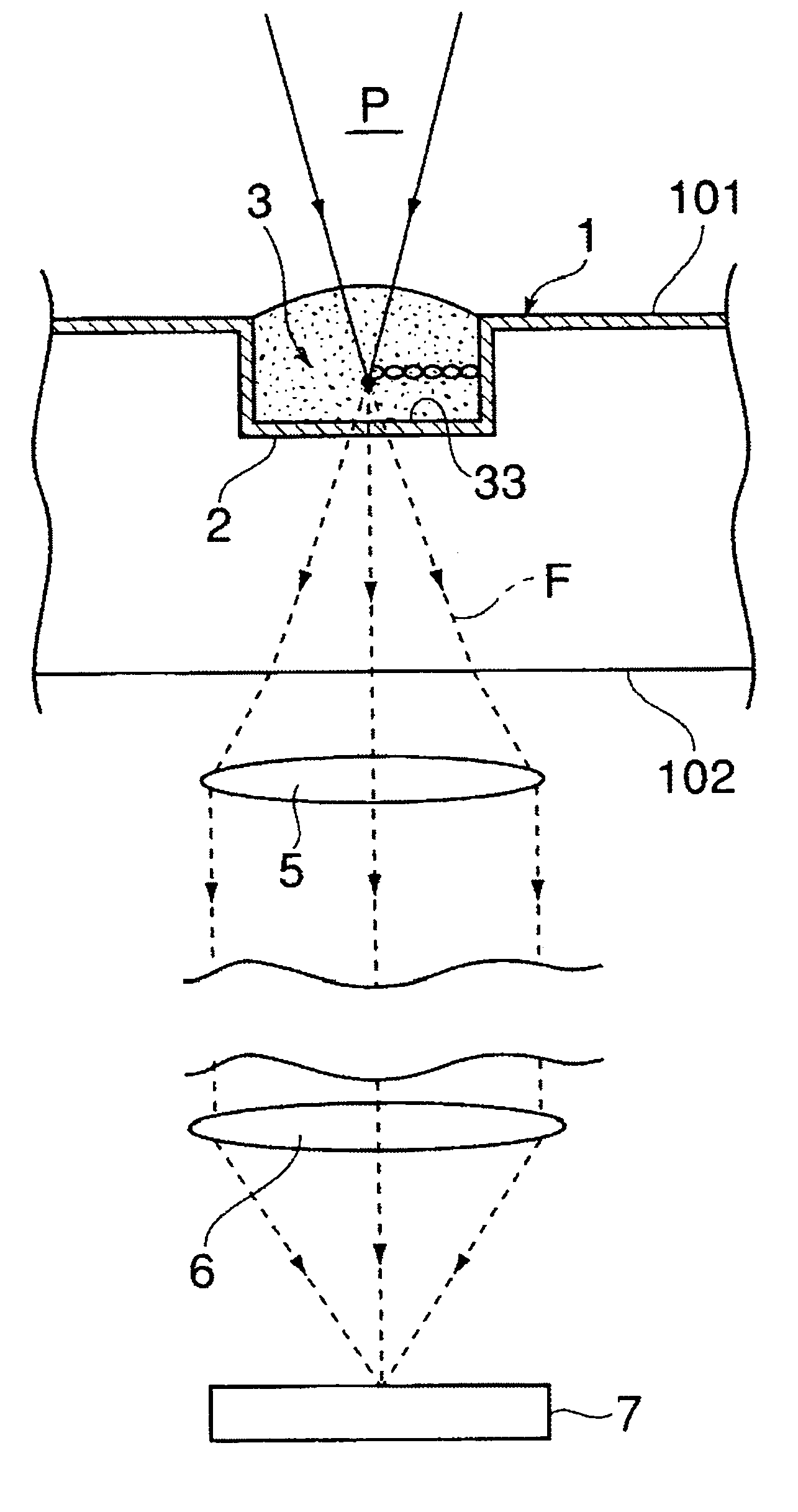
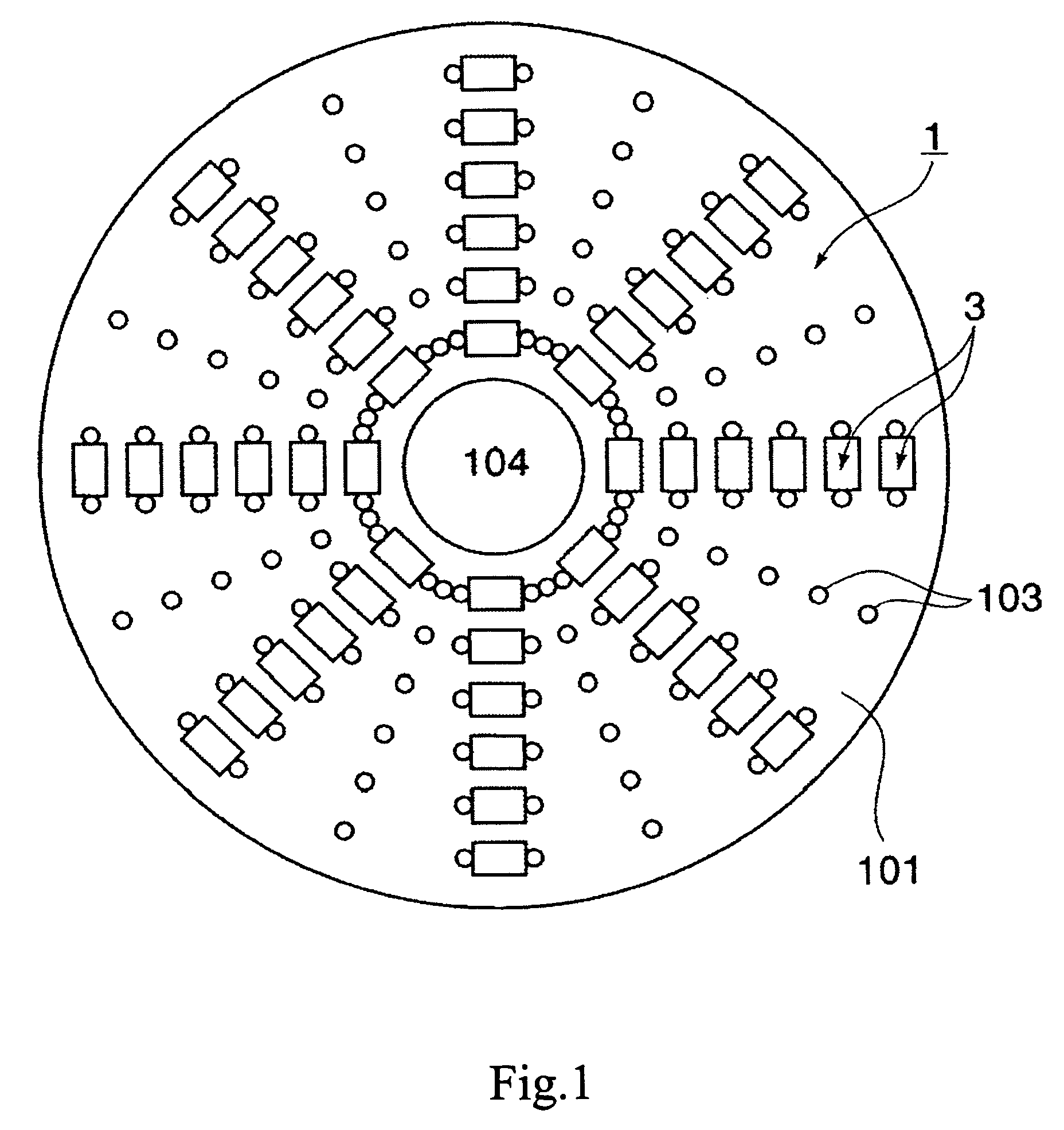
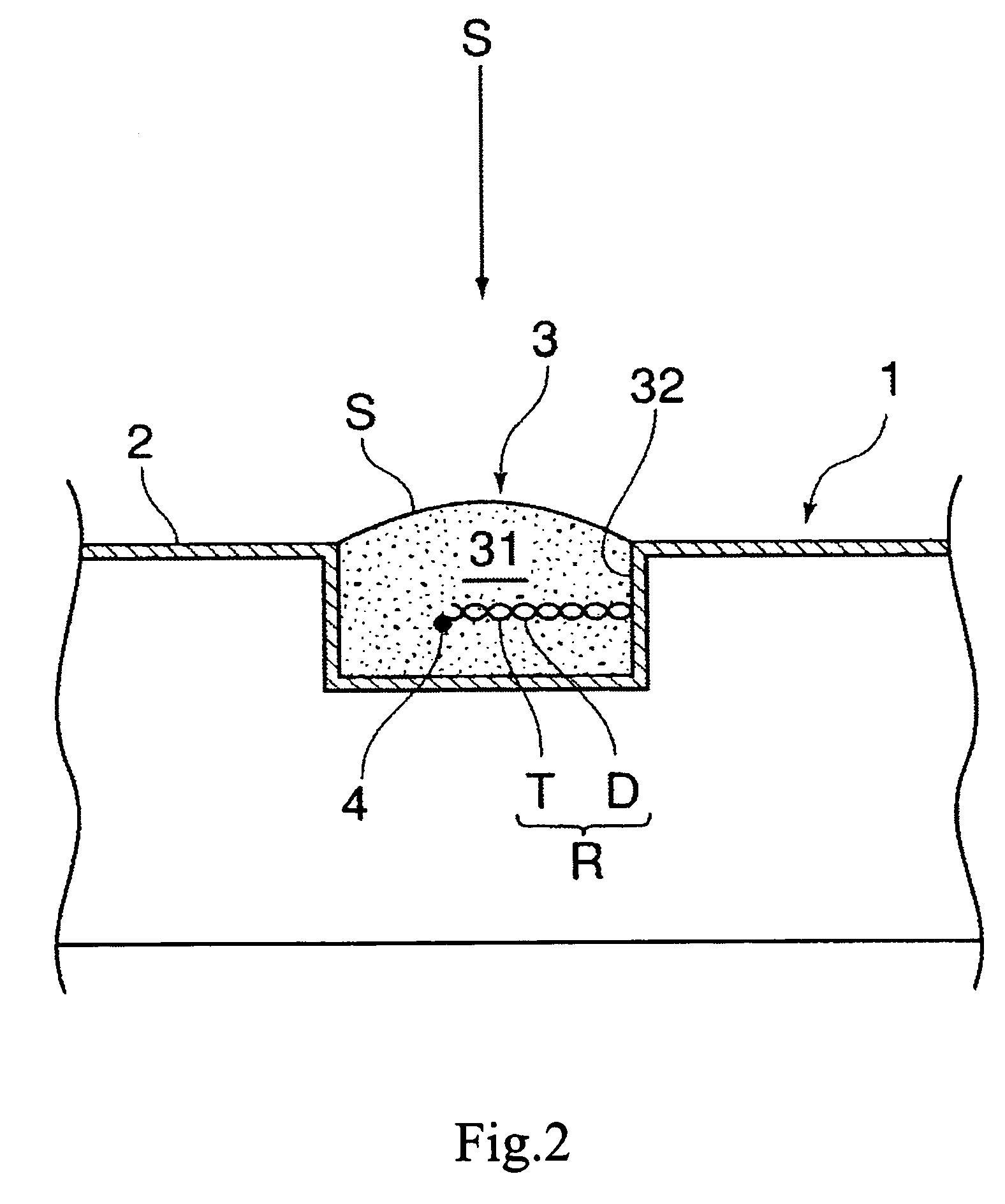
[0035]With reference to the accompanying drawings, a description will hereinafter be made about the construction of the bioassay system according to the present invention. FIG. 1 is a top plan view of a bioassay substrate according to the present invention, which is suited for use on the bioassay system, and FIG. 2 is a schematic view of a detecting section arranged on the substrate and its surrounding area.

[0036]A substrate designated at numeral 1 in FIG. 1 is formed of a material which is adopted for substrates (disks) employed as optical information recording media such as CDs, DVDs or MDs.

[0037]The substrate is formed of silica glass, a silicone, a polycarbonate, polystyrene or any other synthetic resin moldable or otherwise formable into a disk shape, preferably an injection-moldable synthetic resin. Use of economical synthetic resin substrates can achieve low running cost compared with glass chips which have been used conventionally.

[0038]On a front surface 101 of the substrat...


PUM

PropertyMeasurementUnit
wavelengthaaaaaaaaaa
reflectanceaaaaaaaaaa

Abstract

To provide a bioassay system or the like, which can solve the problem of allocating spaces above detecting sections and can also stabilize servo-controlled operation of a disk-shaped plate.Provided is a bioassay system (U) or the like, which is equipped with at least means for immobilizing a nucleotide chain, a peptide, a protein, a lipid, a low molecular-weight compound, a liposome or any other biological substance as a detection substance (D) in a detecting section (3), dropping a target-substance containing solution (S) onto the immobilized detection substance (D), and causing the detection substance (D) and the target substance (T) to interact with each other to prepare a reaction product (R); and means for condensing fluorescence (F), which has been emitted from the fluorescence-labeled substance (D) by irradiating excitation light (P) of a specific wavelength onto the reaction product (R), by a lens (5) arranged on a side of a back surface (102) of the reaction section (3) to determine an intensity of the fluorescence (F).

Description

TECHNICAL FIELD[0001]This invention relates to a bioassay system useful in the field of bioinformatics. More specifically, the present invention is concerned with a bioassay system devised such that fluorescence emitted from a fluorescence-labeled substance existing in a detecting section of prescribed construction is condensed on a back side of the detecting section to determine an intensity of the fluorescence.BACKGROUND ART[0002]Nowadays, molecule-integrated bioassay substrates with predetermined DNAs finely arrayed thereon by microarray techniques, which are generally called DNA chips or DNA microarrays (hereinafter collectively called “DNA chips”), are used in mutation analyses of genes, SNPs (single-base polymorphisms) analyses, gene expression frequency analyses, and the like, and have begun to find utility in a wide variety of fields such as drug developments, clinical diagnoses, pharmacogenomics and forensic medicine.[0003]This DNA chip is characterized in that it permits a...

Claims


Application Information

Patent Timeline
Patent Type & Authority Patents(United States)
IPC IPC(8): G01N33/53C12Q1/00C12Q1/68C12M1/00C12M1/34G01N21/64G01N33/543G01N33/58G01N37/00
CPCG01N21/6428G01N21/645G01N33/54373G01N2021/6482G01N2021/6439C12M1/00G01N33/53G01N33/58
Inventor YAMATSU, HISAYUKIFURUKI, MOTOHIROYAMAMOTO, MASANOBU
Owner SONY CORP
Why Eureka
Try Eureka