
Device, and method for manufacturing the same

a technology of tin crystals and manufacturing methods, applied in thermoelectric devices, natural mineral layered products, instruments, etc., can solve the problems of reducing the yield, reducing the size and weight of memory devices or semiconductor devices, and difficult to manufacture transistors, etc., to achieve the effect of suppressing the variation in the thickness distribution of films, reducing the roughness of tin crystals, and reducing the size and weight of memory devices

Inactive Publication Date: 2010-05-11
SEMICON ENERGY LAB CO LTD
View PDF18 Cites 11 Cited by
  • Summary
  • Abstract
  • Description
  • Claims
  • Application Information

AI Technical Summary

Benefits of technology

The present invention relates to a method for manufacturing a flexible memory device and semiconductor device with a memory element containing a layer containing an organic compound between a pair of electrodes. The method includes forming a stack over a substrate with a separation layer, and separating the stack from the separation layer. The method also includes using an alloy layer containing tin for forming at least one of the electrode layers. The technical effects of the invention include high yield and reliable storage function of the memory device and semiconductor device, as well as improved manufacturing efficiency and flexibility.

Problems solved by technology

Therefore, there is a problem in that yield is decreased due to defects in aligning the metal mask.
Thus, it is difficult to manufacture transistors, memory elements, and solar cells having minute structures, and reduction in size and weight and improvement in performance of a memory device or a semiconductor device are difficult to be achieved.
Moreover, in the case of separating an element which has a layer containing an organic compound by using a separation step shown in Reference 2, there is a problem in that the layer containing an organic compound and a second electrode layer are separated.
As a result, it is difficult to manufacture a memory device and a semiconductor device in which an element including a layer containing an organic compound is provided over a plastic film with high yield.

Method used


Image

  • Device, and method for manufacturing the same
  • Device, and method for manufacturing the same
  • Device, and method for manufacturing the same

Examples


embodiment mode 1

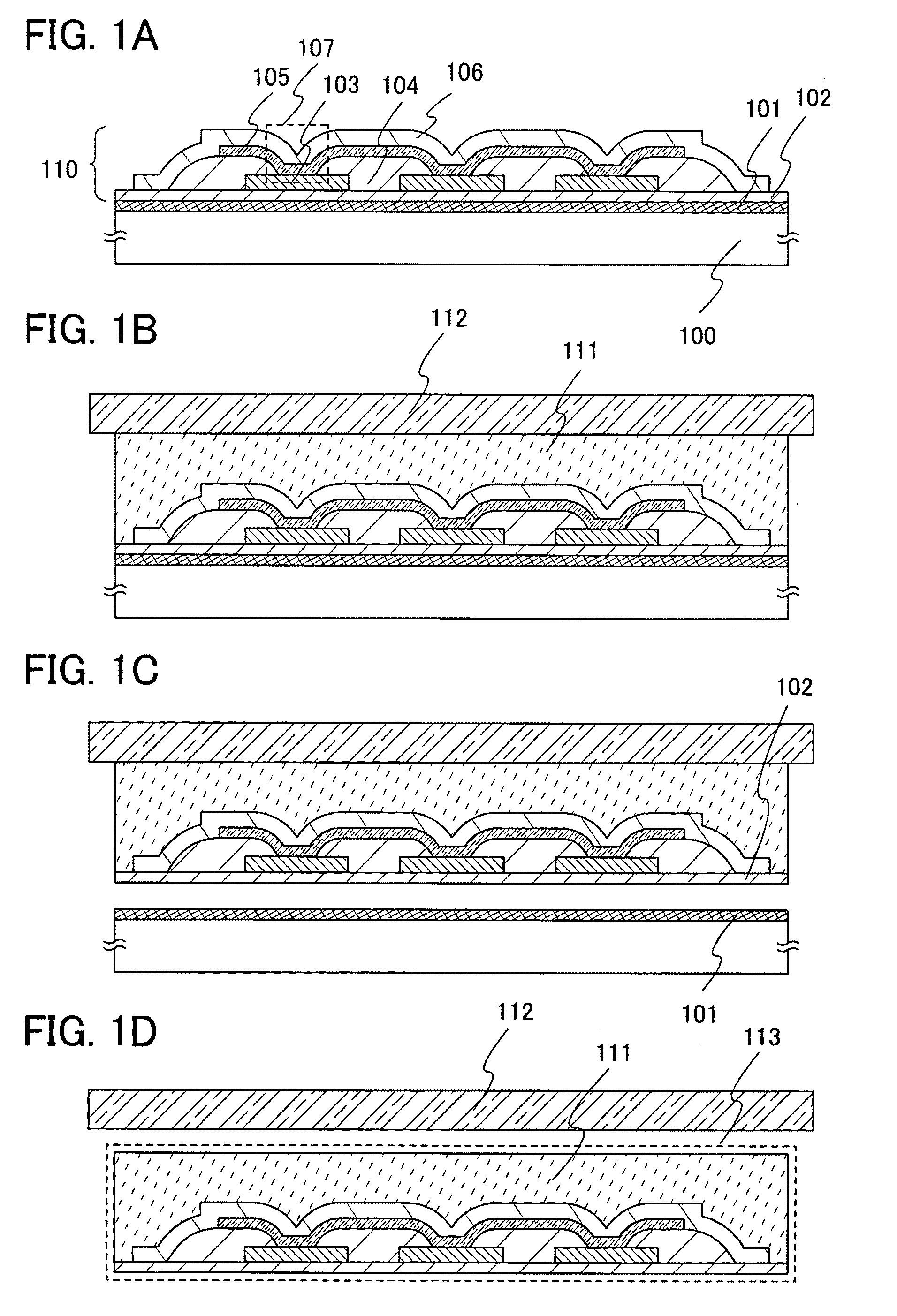
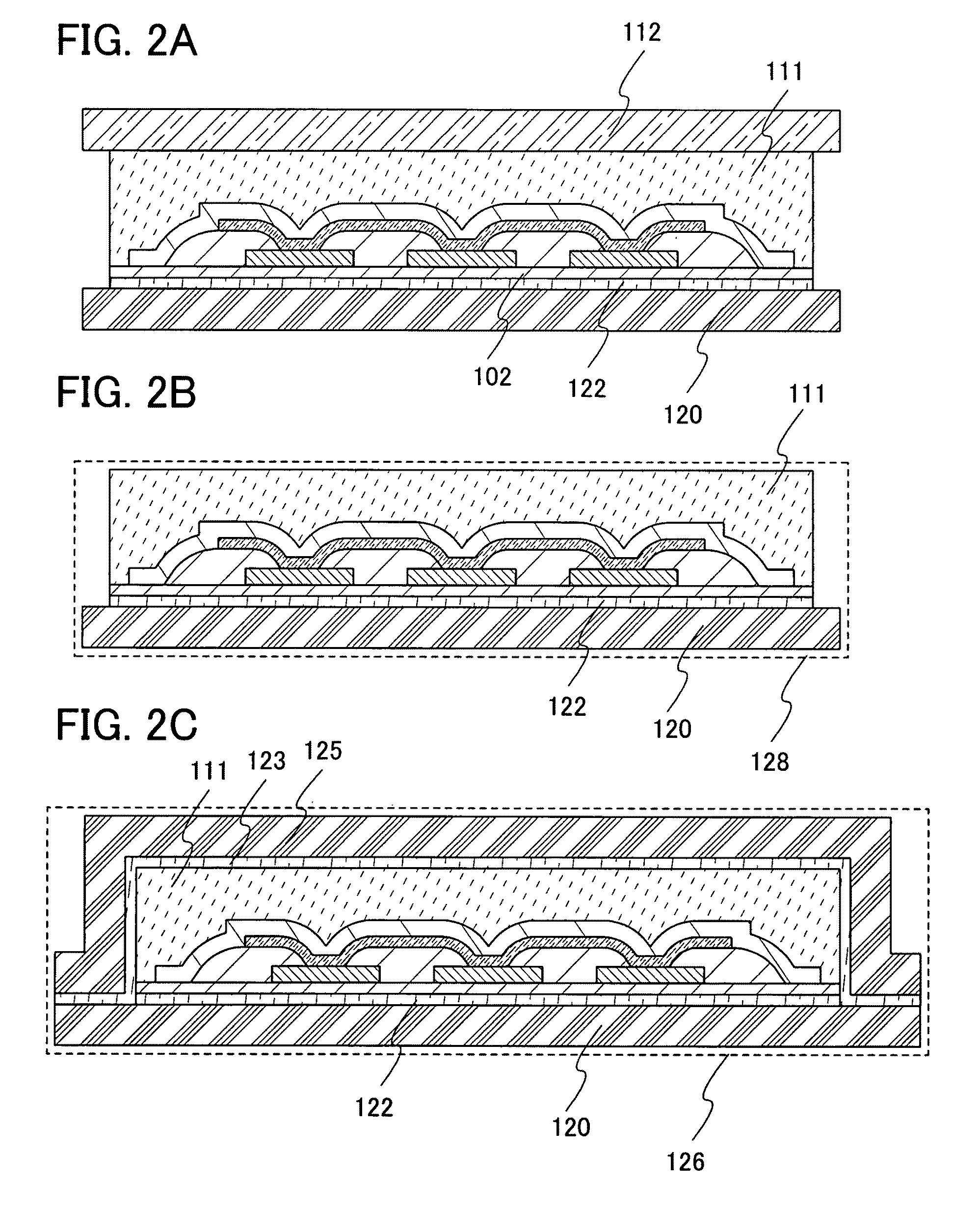
[0053]In this embodiment mode, a main structure of a memory device of the present invention and a manufacturing method thereof will be described. Typically, a method for manufacturing a memory device having a memory cell array, in which memory cells each having a memory element that has a layer containing an organic compound between a pair of electrodes, a first electrode layer and a second electrode layer, are arranged in matrix, will be described with reference to FIGS. 1A to 1D, FIGS. 2A to 2C, and FIGS. 4A to 4C. Also, structures of the memory element will be described with reference to FIGS. 3A to 3F.

[0054]As shown in FIG. 4A, a memory device 127 has a memory cell array 132 and a driver circuit to drive the memory cell array. In the memory cell array 132, memory cells 21 are provided in matrix. The memory cell 21 has a memory element 107 (FIG. 1A). The memory element 107 has, over a substrate 100, a first electrode layer 103 extending in a first direction, a layer 105 containin...

embodiment mode 2

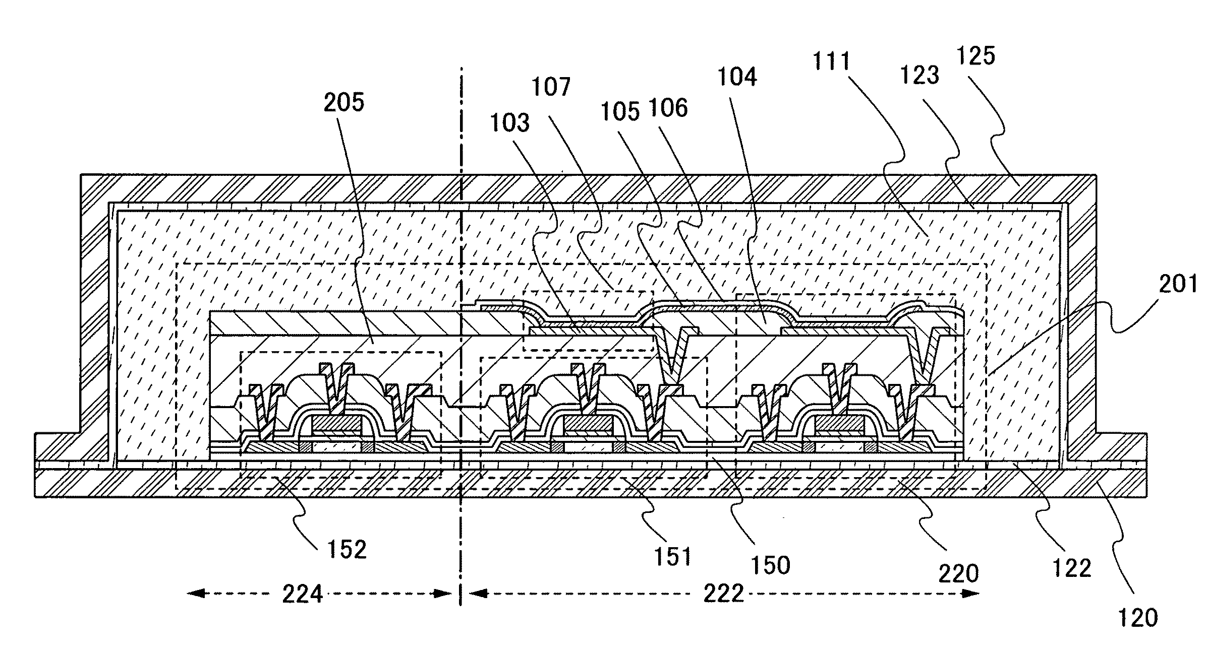
[0134]In this embodiment mode, another mode of the memory device shown in the above embodiment mode formed using a separation method will be described. Typically, a main structure of a memory device having a memory cell array where memory cells each have a switching element and a memory element will be described with reference to FIG. 5 and FIGS. 6A to 6C. FIG. 5 is a cross-sectional view of the memory device in this embodiment mode, and FIGS. 6A to 6C illustrate structures of the memory device in this embodiment mode.

[0135]As shown in FIG. 6A, a memory device 221 in this embodiment mode has a memory cell array 222 and a driver circuit which drives the memory cell array 222. The memory cell array 222 has a plurality of memory cells 220 which are provided in matrix. As shown in FIG. 6A and FIG. 5, in the memory device 221, transistors which form the driver circuit, here a transistor 152 which forms a decoder 224, a transistor 151 which functions as a switching element, and a memory e...

embodiment mode 3

[0156]In this embodiment mode, one mode of the semiconductor device shown in the above embodiment mode formed by a separation method will be described below. Typically, a main structure of a semiconductor device which can perform transmission / reception of instructions or data with radio signals will be described with reference to FIGS. 7 and 8. FIG. 7 is a cross-sectional view of the semiconductor device in this embodiment mode. FIG. 8 illustrates a structure of the semiconductor device in this embodiment mode.

[0157]FIG. 8 is a block diagram illustrating a structural example of the semiconductor device which can perform transmission / reception of instructions or data with radio signals. Such a semiconductor device includes an antenna 312, an RF circuit portion 313, a power supply circuit portion 315, and a logic circuit portion 317 as elements. The antenna 312 transmits and receives signals to / from a communication device which is also called a reader / writer. As a frequency band of ca...


PUM

PropertyMeasurementUnit
lengthaaaaaaaaaa
thicknessaaaaaaaaaa
thicknessaaaaaaaaaa

Abstract

In a method for manufacturing a flexible memory device and semiconductor device, a stack including an element layer and an insulating layer which seals the element layer is formed over a substrate having a separation layer, and the stack is separated from the separation layer. The element layer includes a memory element having a layer containing an organic compound between a pair of electrodes, a first electrode layer and a second electrode layer, and at least one of the pair of electrode layers is formed using an alloy layer containing tin. The flexible memory device and semiconductor device include a memory element having a layer containing an organic compound between a pair of electrodes, a first electrode layer and a second electrode layer, in which at least one of the pair of electrode layers is formed using an alloy layer containing tin.

Description

TECHNICAL FIELD[0001]The present invention relates to a device provided with a memory element which includes a layer containing an organic compound, and also relates to a manufacturing method of the device.BACKGROUND ART[0002]It has been required to manufacture semiconductor devices at low cost, and development has been extensively carried out in recent years on elements such as transistors, memory elements, and solar cells which use layers containing organic compounds for control circuits, memory circuits, and the like (refer to Reference 1: Japanese Published Patent Application No. 2006-148080).[0003]Various applications of semiconductor devices having the elements such as transistors, memory elements, and solar cells which use the layers containing organic compounds are expected. And, compact and lightweight semiconductor devices have been developed by using flexible plastic films instead of non-flexible substrates, e.g., glass substrates or silicon wafers.[0004]Since plastic fil...

Claims


Application Information

Patent Timeline
Patent Type & Authority Patents(United States)
IPC IPC(8): G06K21/06
CPCG11C13/0016G11C13/004H01L51/105H01L51/0591H01L27/283H01L51/006H10K19/10H10K85/633H10K10/50H10K10/84
Inventor YUKAWA, MIKIOSUGISAWA, NOZOMUNAGATA, TAKAAKIYOSHITOMI, SHUHEIAIZAWA, MICHIKO
Owner SEMICON ENERGY LAB CO LTD
Learn More