Air separation module with load carrying center tube

a technology of air separation module and center tube, which is applied in the direction of separation process, membrane, manufacturing tools, etc., can solve the problems of inability to achieve combustion, inability to sustain combustion, and inability to meet the conditions of combustion, so as to eliminate the problem of tolerance accumulation and eliminate a significant portion of the thermal growth concern

Active Publication Date: 2010-05-18
PARKER INTANGIBLES LLC
View PDF18 Cites 20 Cited by
  • Summary
  • Abstract
  • Description
  • Claims
  • Application Information

AI Technical Summary

Benefits of technology

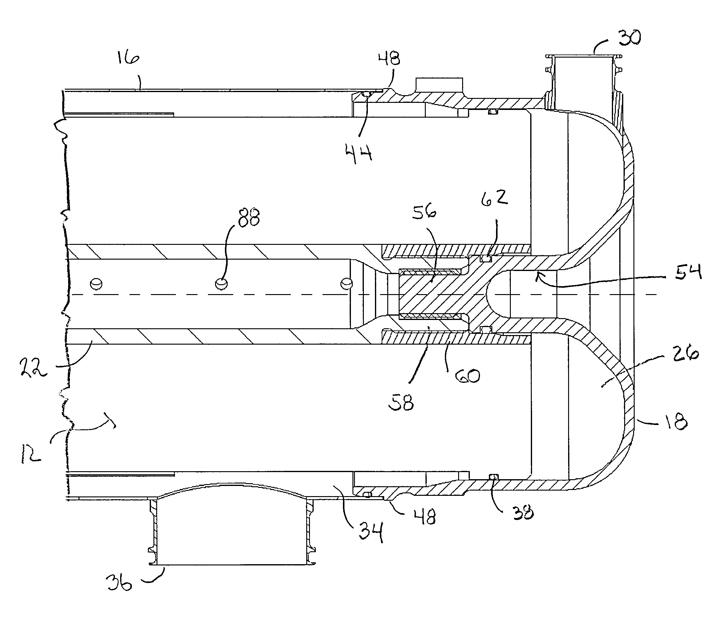
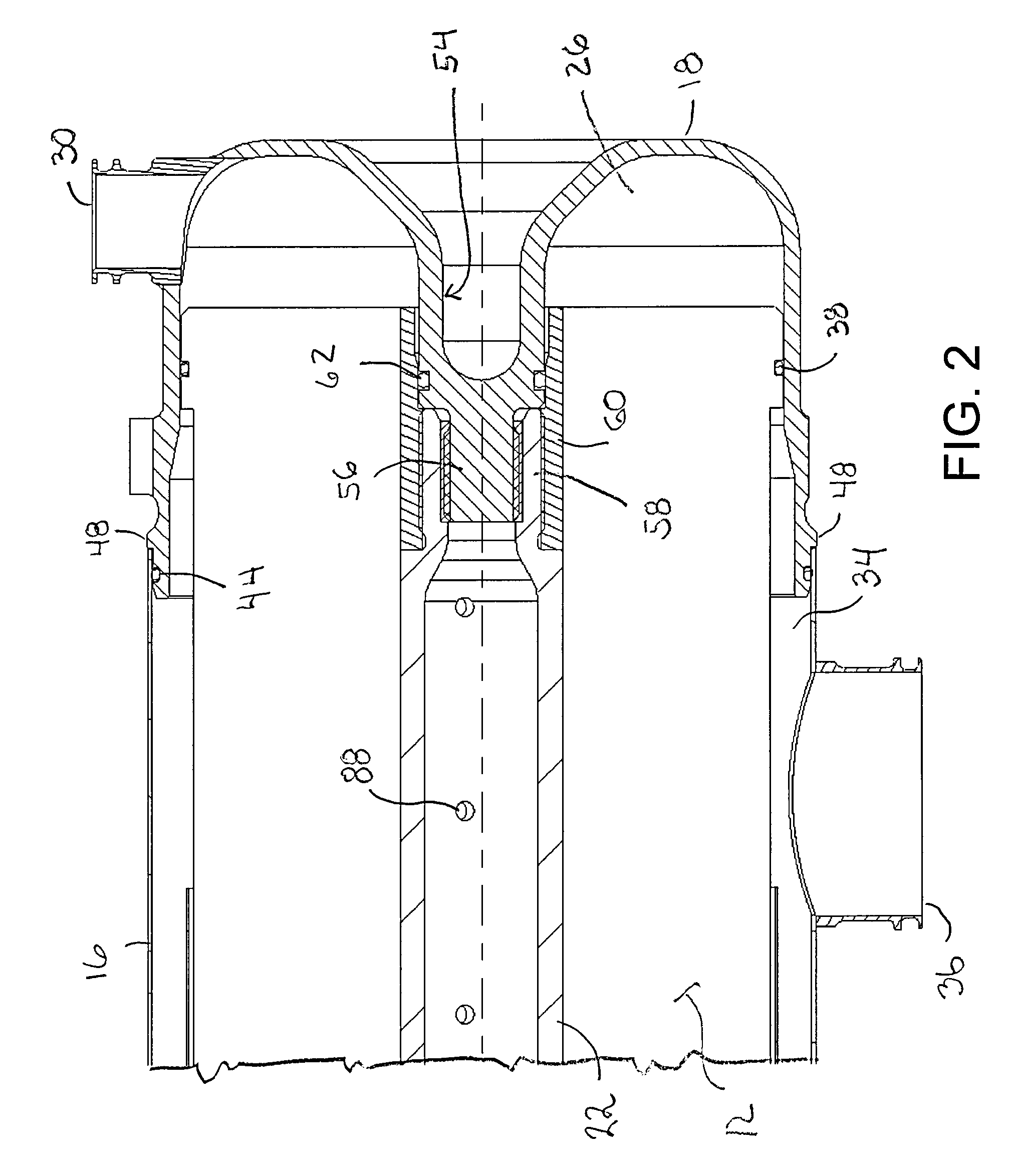
[0010]The present invention provides a novel and inventive approach for providing the mechanical ASM housing to address the large tolerance accumulations, thermal growth, pressure containment and aircraft induced vibrations issues. This approach utilizes the center tube of a hollow membrane fiber bundle as a structural element for the housing design. This allows the pressure vessel end caps to be mechanically coupled to the fiber bundle via the center tube, thus eliminating the tolerance accumulation issue and eliminating a significant portion of the thermal growth concerns. Further in accordance with the invention, the ASM preferably incorporates a “floating” external tube to provide a pressure containment feature of the ASM and / or an anti-rotation feature to prevent the end caps from loosening due to the aircraft vibration environment. The tube may be sealed on either end by O-rings to provide pressure containment, while allowing the fiber bundle and end caps to move axially due to thermal expansion or contraction. The remaining thermal growth concern can be resolved by a “dagger pin” incorporated in one end of the housing that allows for a sliding fit between the aircraft structure and the ASM housing.
[0011]This design approach optimizes the overall weight of the ASM by allowing for the most compact design with the fewest number of components. Additionally, the assembly time of a preferred ASM assembly is optimized by eliminating procedures such as welding, curing time for sealants, and / or specialized assembly fixtures, such as those used for riveting. Provision can also be made for easy disassembly of the ASM in the event that a unit, such as when the ASM fails to meet the required performance defined in an end item acceptance test procedure.

Problems solved by technology

If any one of these three items is not present in sufficient quantities, combustion cannot take place or be sustained.
A fire in the ullage creates a rapid pressure rise (an explosion) in the fuel tank that causes a structural failure of the airframe.
As in-tank fires are rare events indeed, it suggests that while these three items may be present in the fuel tank, the conditions for combustion are not easily satisfied.
The challenge of the fuel tank inerting problem is to blanket the ullage space in the fuel tank with an appropriate amount of nitrogen to prevent combustion.
The inerting of an airplane fuel tank presents a significant design challenge to provide a desired level of fuel tank safety at the lowest penalty to the airplane.
The penalty to the airplane comes in the form of inerting system weight, parasitic losses, and cooling losses.
Due to the dimensional variations of producing a hollow membrane fiber bundle, the ASM housing becomes more complex driving both weight and cost into the overall ASM design.
The current methods for addressing the large tolerance accumulations, thermal growth, pressure containment and aircraft vibration environments have negatively impacted the weight and cost of the ASM.

Method used


Image

  • Air separation module with load carrying center tube
  • Air separation module with load carrying center tube
  • Air separation module with load carrying center tube

Examples


Embodiment Construction

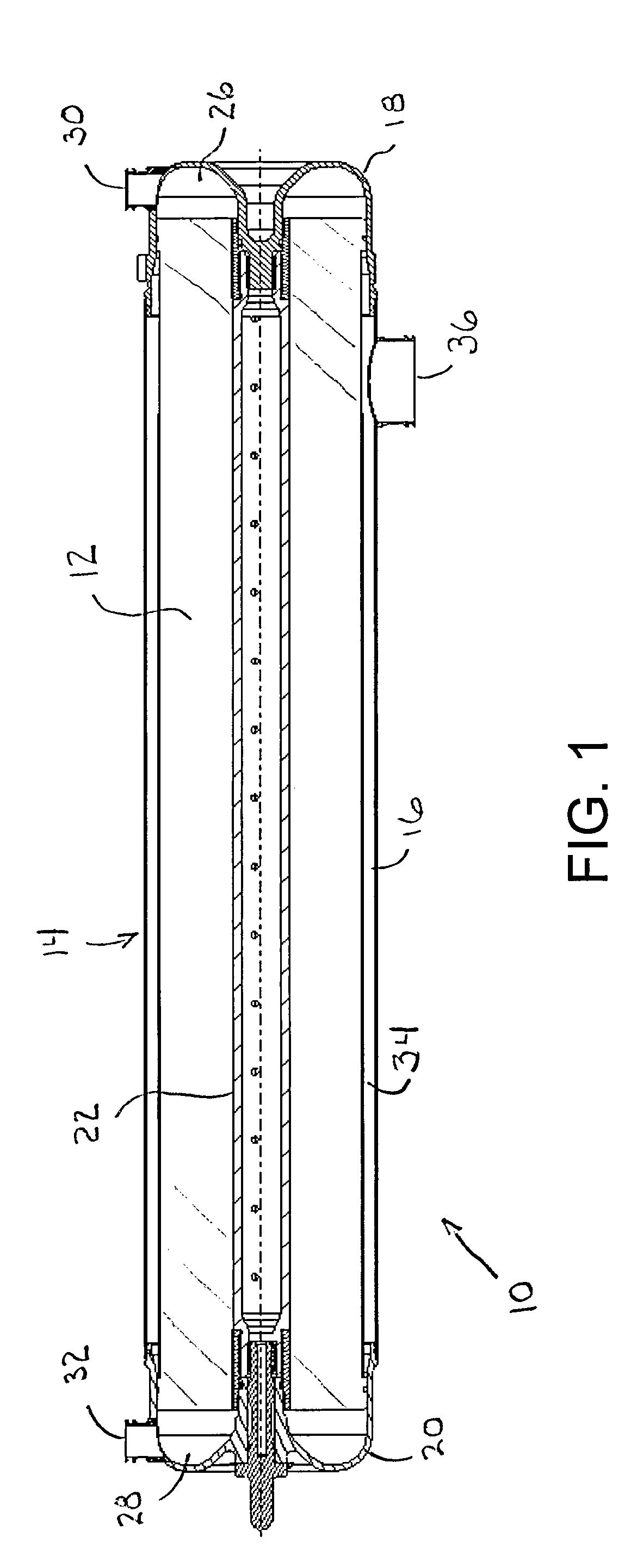
[0022]Referring now in detail to the drawings and initially to FIG. 1, an exemplary air separation module (ASM) according to the invention is indicated generally at 10. The ASM 10 generally comprises a bundle 12 of hollow elongated fiber membranes, and a pressure vessel 14 (herein also referred to as a housing) enclosing the bundle 12. The pressure vessel 14 includes an outer tube 16, end caps 18 and 20 at opposite ends of the tube, and an inner tube 22 located within the fiber bundle 12.

[0023]In the illustrated embodiment, each hollow fiber membrane of the bundle 12 has opposite ends opening to respective chambers 26 and 28 at the ends of the pressure vessel 14 which communicate with respective ports 30 and 32. Accordingly, the fiber membranes provide a flow path for a mixture of gases from one end chamber to the other. The end chambers are isolated from an interior collection chamber 34 through which the hollow fiber membranes pass, and thus the interior flow passages of the hollo...


PUM

PropertyMeasurementUnit
thermal expansionaaaaaaaaaa
pressure riseaaaaaaaaaa
pressureaaaaaaaaaa

Abstract

An air separation module comprising a bundle of hollow elongated membranes, and a pressure vessel enclosing the bundle. The pressure vessel includes an outer tube, end caps at opposite ends of the tube, and an inner tube located within the fiber bundle. The inner tube is fixedly mechanically connected at opposite ends to the end caps to form a structural spine of the pressure vessel, whereby loads acting on the air separation module are transferred between the end caps primarily by the center tube.

Description

RELATED APPLICATIONS[0001]This application claims the benefit of U.S. Provisional Application No. 60 / 727,776 filed Oct. 18, 2005, which is hereby incorporated herein by reference.FIELD OF THE INVENTION[0002]The invention herein described relates to gas separation modules and more particularly to air separation modules useful in inerting systems such as those employed in aircraft.BACKGROUND[0003]In general, the phenomenon of combustion or fire requires three items to be present: fuel, oxidizer and an ignition source. These three items represent the verticies of the so-called “fire triangle”. If any one of these three items is not present in sufficient quantities, combustion cannot take place or be sustained.[0004]Aircraft fuel tank explosions can occur when these three items are present in the ullage space above the liquid fuel in the fuel tank. A fire in the ullage creates a rapid pressure rise (an explosion) in the fuel tank that causes a structural failure of the airframe. In this...

Claims


Application Information

Patent Timeline
Patent Type & Authority Patents(United States)
IPC IPC(8): B01D53/22
CPCB01D63/02B64D37/32B01D2313/20Y10T29/49826Y02T50/44B01D2313/21Y02T50/40
Inventor SEMMERE, DANLINKER, DAN E.PEARSON, SCOTT D.
Owner PARKER INTANGIBLES LLC
Why Eureka
Try Eureka