Method and apparatus for computing interpolation factors in sample rate conversion systems

a sample rate conversion and factor technology, applied in the field of digital signal processing, can solve the problems of reducing the reliability of the system, limiting the circuit to scaling the sampling rate by a rational number, and limiting the range of values of d, so as to increase the system reliability, simplify the requirements, and simplify the effect of the digital signal processing

Active Publication Date: 2010-05-18
TERADYNE
View PDF7 Cites 55 Cited by
  • Summary
  • Abstract
  • Description
  • Claims
  • Application Information

AI Technical Summary

Benefits of technology

[0008]An ability to process data accurately in a three clock system allows for simplification of the requirements for real analog clock generation by adding complexity to the digital signal processing. In general, reductions in analog complexity are desirable because they lead to increased system reliability, greater flexibility of functionality, and lower system cost.

Problems solved by technology

This process is referred to generally as “decimation.” It is limited, though, to situations in which the sampling rate of the input is an integer multiple of the sampling rate of the output.
Such a circuit is, however, limited to scaling the sampling rate by a rational number.
More importantly, for a digital system, there are practical limits on the ranges of values for D and I. The decimation factor D can not be so large that the decimated signal no longer satisfies the Nyquist rate.
Additionally, the interpolation factor I cannot be made arbitrarily large, because the required complexity of the interpolation filter increases as I gets larger (e.g., more taps).
Maintaining consistency between the different sample rate clocks in such situations places a burden on the accuracy and complexity of the hardware of the timing system.

Method used


Image

  • Method and apparatus for computing interpolation factors in sample rate conversion systems
  • Method and apparatus for computing interpolation factors in sample rate conversion systems
  • Method and apparatus for computing interpolation factors in sample rate conversion systems

Examples


Embodiment Construction

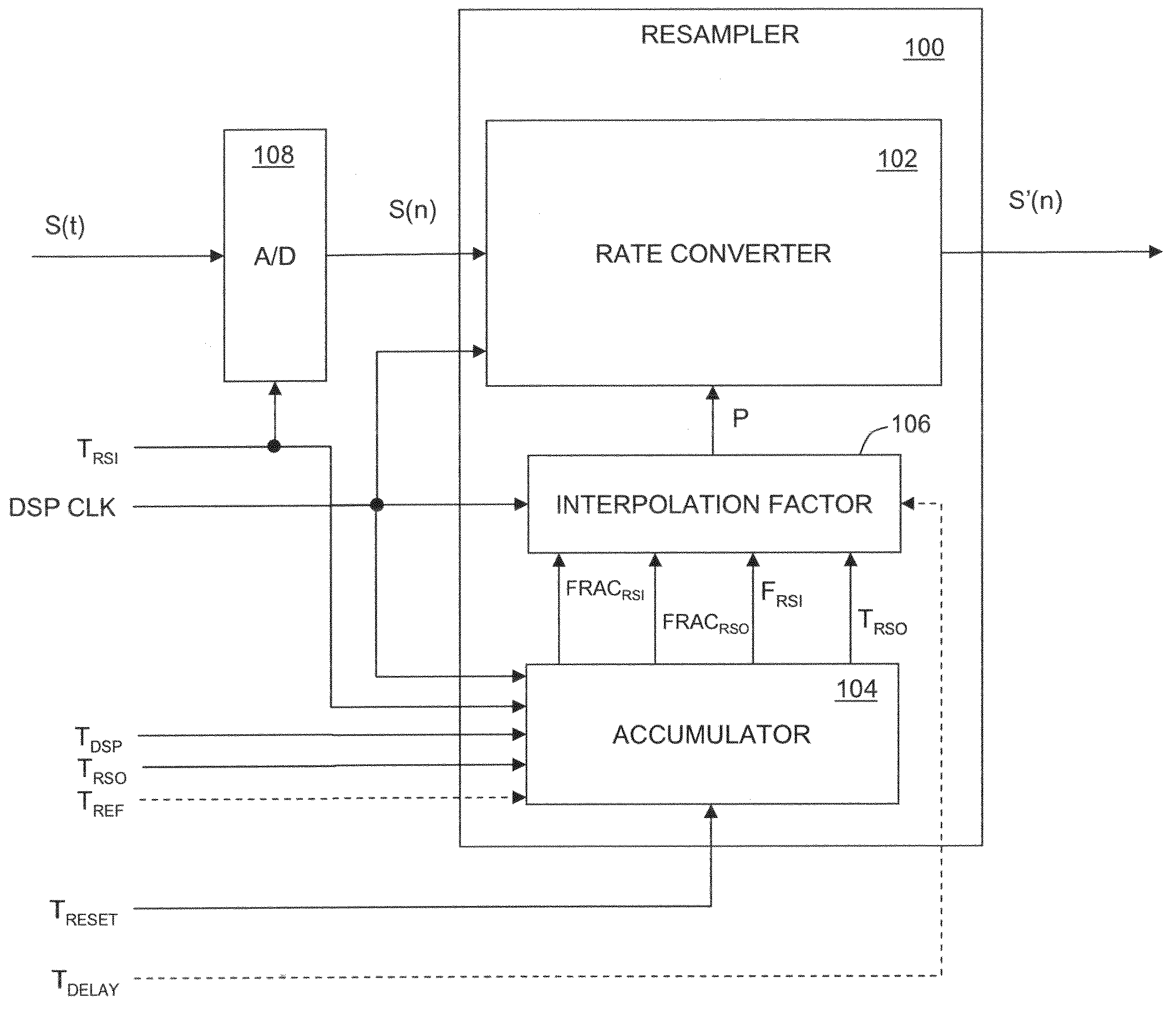
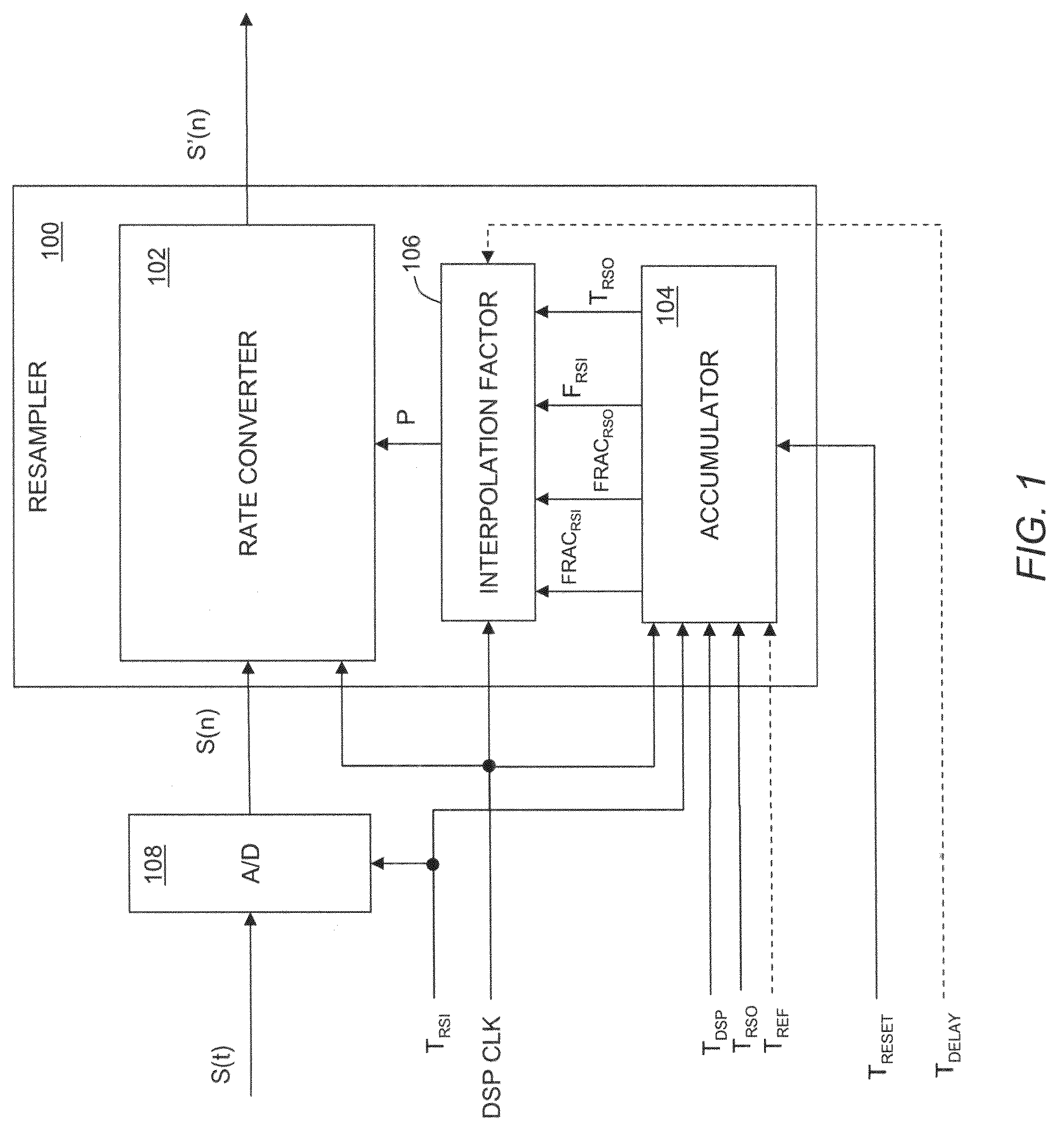
[0026]Systems and processes for converting data at one sample rate to data at a second sample rate are described herein. In the prior art, implementations of sample rate conversion systems employ a digital signal processing clock that is equal to, or directly related to, as in an integer multiple of, the output sample rate. Beneficially, in the system and techniques described herein allow for a system processing clock having non-trivial M / N relationship to the output sample rate. For example, M and N can be very large integers. In at least some embodiments, a programmable time delay (having arbitrary range and resolution) can also be applied to the output signal.

[0027]In general, the techniques described herein can be applied to any real-time system having fixed converter frequencies, variable (or even fixed, but different) signal data rates. Use of the term converters, generally includes analog-to-digital converters (ADC) and digital-to-analog converters (DAC), depending upon the p...


PUM


Abstract

The invention allows the interpolation factor, a critical parameter in sample rate conversion systems, to be computed in a real-time system where there is a complex relationship between a DSP clock and the data clocks. Typically, two or three of the clocks in such a system will have simple relationships (such as CLOCK1=2*CLOCK2). This relationship leads to degenerate cases where, in fact, there are only one or two clocks to consider rather than three. Furthermore, the invention allows for input data rates that are higher than the DSP clock rate. The invention also provides for an arbitrary time delay to be applied to the output signal.

Description

RELATED APPLICATIONS[0001]This application claims the benefit of priority to U.S. Provisional Patent Application Ser. No. 60 / 988,772, filed Nov. 16, 2007, the entire contents of which are incorporated herein by reference.FIELD OF THE INVENTION[0002]This invention relates generally to digital signal processing and more particularly to converting a digital signal at a first sampling rate to a representation of the same digital signal at a second sampling rate.BACKGROUND OF THE INVENTION[0003]In many electronic applications, signals are represented and processed digitally. Digital words, or samples, represent the value of the signal at a regular time interval. This regular interval is often referred to as the sample rate, and is typically expressed in units of Hertz (Hz) representing the reciprocal of the sample interval time period. The signal thus represented can have no energy above half the sample rate; the frequency equal to half the sample rate is called the Nyquist frequency.[00...

Claims


Application Information

Patent Timeline
Patent Type & Authority Patents(United States)
IPC IPC(8): H03M7/00
CPCH03H17/0685H03H17/0642
Inventor ROSENTHAL, DANIEL A.NAZARIAN, COREY A.
Owner TERADYNE
Why Eureka
Try Eureka