
Vibration damping apparatus for windows using viscoelastic damping materials

a technology of viscoelastic damping and vibration damping apparatus, which is applied in the direction of shock absorbers, roofs, transportation and packaging, etc., can solve the problems of significant vibration and acoustic energy, and achieve the effect of enhancing air-film vibration damping of reducing acoustic energy and/or vibrational energy of window structures

Active Publication Date: 2010-05-25
DAMPING TECH
View PDF53 Cites 17 Cited by
  • Summary
  • Abstract
  • Description
  • Claims
  • Application Information

AI Technical Summary

Benefits of technology

[0014]Accordingly, it is an advantage of the present invention to provide a vibration damping system that can reduce the acoustic energy and / or vibrational energy of window structures, including windows used in vehicles, aircraft, spacecraft, and even vessels.
[0015]It is another advantage of the present invention to provide a vibration damping system in which a space is formed between a first portion of two layers of material in a window structure, in which this space has predetermined dimensions to enhance air-film vibration damping of acoustic energy and / or vibrational energy in the window structure, and in which a viscoelastic material is placed between the two layers of material at a second portion.
[0016]It is still another advantage of the present invention to provide a vibration damping system for window structures which uses a gaseous material as a vibration damping medium, within a space of predetermined dimensions that is part of the window structure, and uses a viscoelastic material as a vibration damping medium at a different portion of the window structure.
[0017]It is a further advantage of the present invention to provide a vibration damping system for window structures using a gaseous material within a space of predetermined dimensions and using a viscoelastic material at a different location of the window structure, and in which at least a portion of the window structure is essentially optically clear, whereas a portion of the window structure may not be substantially clear at optical wavelengths.
[0018]It is still a further advantage of the present invention to provide a vibration damping system for window structures that includes a predetermined space between at least two layers of window structure material, and includes a viscoelastic material at a different portion between the layers of window structure material, in which one of the window structures exhibits an opening that extends completely therethrough for pressure equalization.
[0019]It is yet a further advantage of the present invention to provide a vibration damping system for window structures that includes a space of a predetermined dimension between at least two window structures, and includes a viscoelastic material at a different portion between the layers of window structure material, in which the space has a gaseous material therewithin, and in which the gaseous material is pressurized.

Problems solved by technology

The resonance response of such window structures results in significant vibration and acoustic energy which typically contributes significantly to the interior noise in automobiles or other vehicles, and in aircraft cabins.

Method used


Image

  • Vibration damping apparatus for windows using viscoelastic damping materials
  • Vibration damping apparatus for windows using viscoelastic damping materials
  • Vibration damping apparatus for windows using viscoelastic damping materials

Examples


embodiment 400

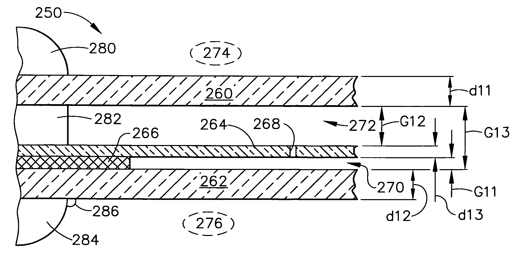
[0102]A layer of viscoelastic material 466 is positioned between the exterior pane 460 and a portion of the intermediate pane structure 464. In a similar fashion to the embodiment 400 depicted in FIG. 10, this layer of viscoelastic material 466 is rather narrow or “thin” as compared to the gap dimension G51. This may or may not have superior characteristics in some applications, but perhaps there are situations in which this would be superior with respect to an appropriate gap distance G51 for certain types of window structure vibration damping applications.

[0103]Referring now to FIG. 12, still another alternative embodiment 500 is illustrated as having a main exterior member 510 that is in contact with the exterior environment 524, a main interior member 512 that is in contact with the interior environment 526, and an intermediate member 514 that provides an air-film vibration damping characteristic with respect to the exterior member 510. Intermediate member 514 provides a spaced-...

embodiment 650

[0110]Of course, the windows can be made any size desired by a designer, and the two window structures 600 and 650 of FIGS. 13 and 14 are depicted as a direct comparison of the same size of a viscoelastic layer, which is not at all a requirement for use with the present invention. The window structure 650 could always be made larger, by increasing the inner dimensions of the viscoelastic layer 266. However, that would also tend to increase the size for the overall structure of the window, which might lead to a different style of cabin interior trim or fuselage structure, and may also affect the spacings of the windows for aesthetic purposes. Since the smaller viewing area may need to be increased, there may be fewer windows per fuselage length, when using the embodiment 650 of FIG. 14, with respect to a particular amount of vibration damping within certain frequency ranges. This is a matter of design choices, assuming sufficient vibration damping is achieved for a range of window si...


PUM


Abstract

An improved vibration damping system is provided for use with window structures. The window damping system employs both air-film damping technology and viscoelastic damping materials to increase mechanical and / or acoustic vibration damping in window structures.

Description

TECHNICAL FIELD[0001]The present invention relates generally to vibration damping equipment and is particularly directed to damping devices of the type which can damp mechanical and / or acoustic vibrations in windows. The invention is specifically disclosed as a window damping system that employs both air-film damping technology and viscoelastic damping materials to increase damping in the window structure.BACKGROUND OF THE INVENTION[0002]Windows of vehicles and aircraft typically have a relatively large surface area and, therefore, have good acoustic radiation efficiency. The resonance response of such window structures results in significant vibration and acoustic energy which typically contributes significantly to the interior noise in automobiles or other vehicles, and in aircraft cabins. Particularly for aircraft, turbulent air flow at the exterior surfaces of the fuselage skin and the exterior surfaces of the windows tends to excite these resonances.[0003]In typical conventiona...

Claims


Application Information

Patent Timeline
Patent Type & Authority Patents(United States)
IPC IPC(8): F16F7/00
CPCF16F15/0232F16F9/306
Inventor LEWIS, THOMAS M.PARIN, MICHAEL L.
Owner DAMPING TECH
Learn More