Expandable surgical reaming tool

a reaming device and expandable technology, applied in the field of reaming devices, can solve the problems of loss of hip motion, bone under the cartilage layer is exposed, cartilage wearout, etc., and achieve the effect of effective reaming/cutting

Inactive Publication Date: 2010-05-25
BOTIMER GARY
View PDF18 Cites 13 Cited by
  • Summary
  • Abstract
  • Description
  • Claims
  • Application Information

AI Technical Summary

Benefits of technology

[0013]The present invention relates to an expandable reaming device for reaming, cutting, or drilling, which has one or more moveable blades for increasing the effective diameter of the reamer head. The expandable device may be adapted for reaming an acetabulum in preparation for implanting a prosthetic component, such as an acetabular cup or socket, during a hip arthroplasty. The preferred reaming device comprises blades or blade portions that, individually or together, provide a greater-than-180-degree cutting edge(s), so that, upon rotation of the reamer head, the device may ream a hemisphere in a surface even if the rotational axis of the device is not parallel to the axis of the concave surface being reamed / cut. During a hip arthroplasty, this offers greater flexibility in placement of the shaft of the reaming device relative to the center of axis of the acetabulum, and, hence, is advantageous for MIS hip arthroplasty
[0017]In one preferred embodiment, the moveable, “expanding blade(s)” comprise two parallel blades that remain parallel to each other and to the rotational axis throughout expansion, the blades each being greater than 180 degrees in circumference and each generally forming a segment of a sphere. As the expanding blades move outward, perpendicularly to their respective blade planes, the effective diameter of the reaming head increases and the reaming head may ream / cut increasingly larger-diameter partial spheres. The expanding blades are preferably raised as they are moved outward, to maintain the effective reaming / cutting shape of the reaming head very close to a perfect partial sphere.
[0019]In an alternative embodiment, two expanding blades start, when the reamer head is contracted, generally parallel to the rotational axis of the device, and then expand by pivoting out and down generally perpendicularly to their respective blade planes. Thus, the two blades, at the start of reaming, are generally parallel, and are pivoted generally outward during expansion to become non-parallel to each other and non-parallel to the rotational axis. The blades preferably are each greater than 180 degrees in circumference and each generally form a segment of a sphere. As the expanding blades move outward, the effective diameter of the reaming head increases and the reaming head may ream / cut increasingly larger-diameter partial spheres. The expanding blades maintain the effective reaming / cutting shape of the reaming head very close to a perfect partial sphere throughout expansion.

Problems solved by technology

If the surface cartilage is badly damaged, or if the joint surfaces are not aligned properly, then the cartilage will wear out, and as a result, the bone under the cartilage layer is exposed.
The combination of these factors cause pain and will eventually result in the loss of motion of the hip.
The process of replacing reamer heads multiple times during a surgery is time consuming, inefficient, inconvenient, and may also lead to surgical errors in that the angle of acetabular penetration may not be accurately preserved during each reamer head substitution.
However, this exposure comes at the expense of trauma to the muscle and tendons and of considerable postoperative pain, requiring inpatient stay and delay of postoperative physical therapy.
With a small incision, it is more difficult to place the acetabular reamer in direct alignment with the axis of the acetabulum.

Method used


Image

  • Expandable surgical reaming tool
  • Expandable surgical reaming tool
  • Expandable surgical reaming tool

Examples


Embodiment Construction

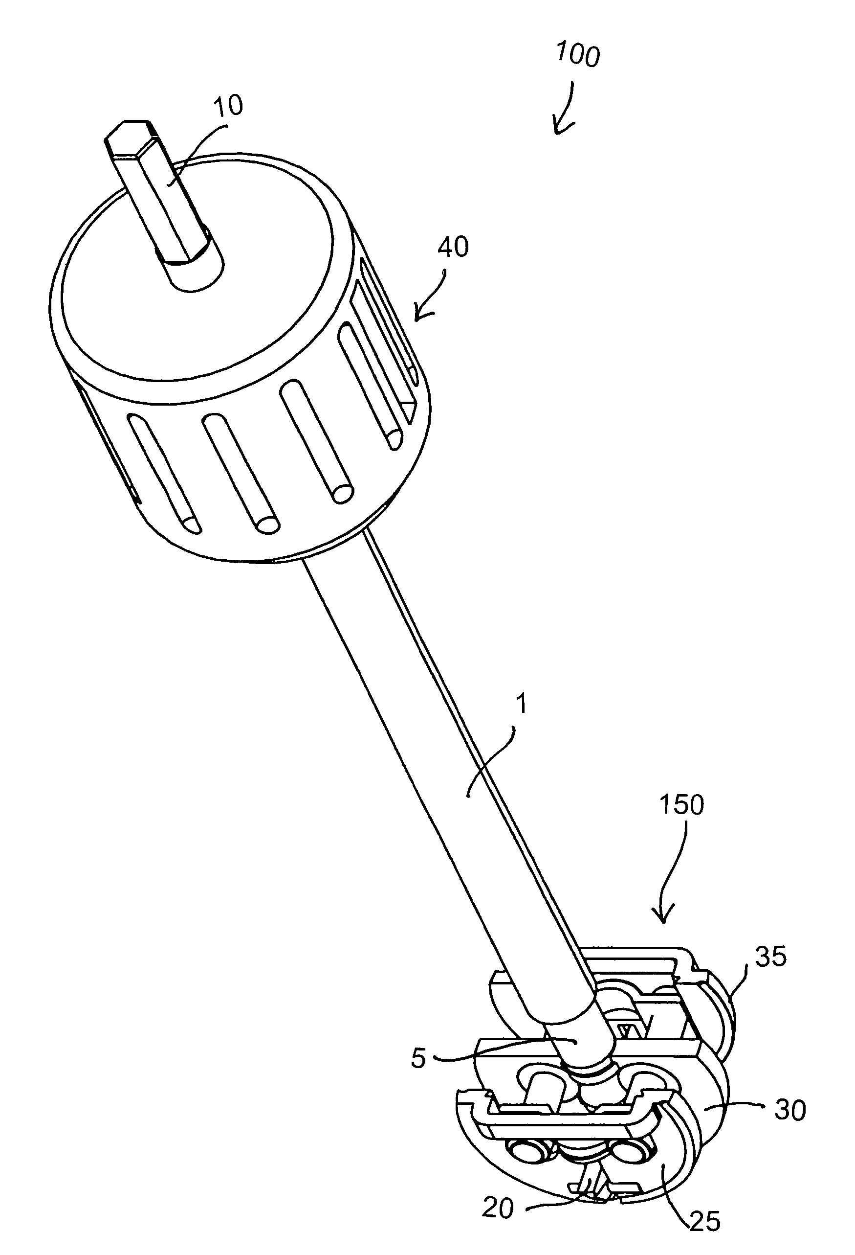
[0081]Referring to the figures, there are shown several, but not the only, embodiments of the invented expandable reaming device. While the preferred embodiments are especially-well adapted for reaming an acetabulum in hip arthroplasty, the preferred or other embodiments may be useful for other reaming, cutting, and drilling applications, both in the human body, animals, and / or other applications including non-surgical applications. Therefore, the terms “reaming,”“cutting,” and “reaming device” are not intended to limit the invented device to a particular medical procedure.

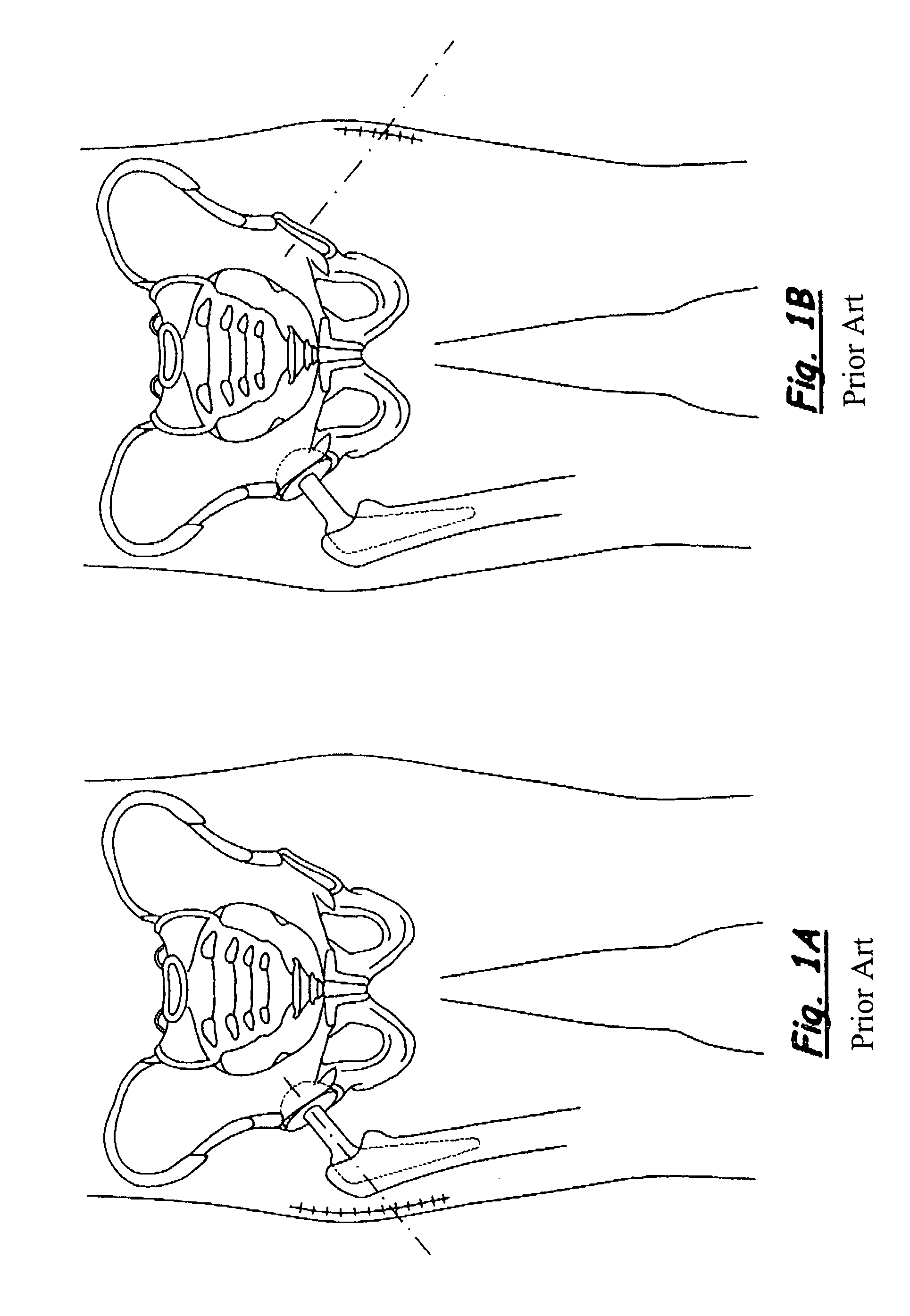
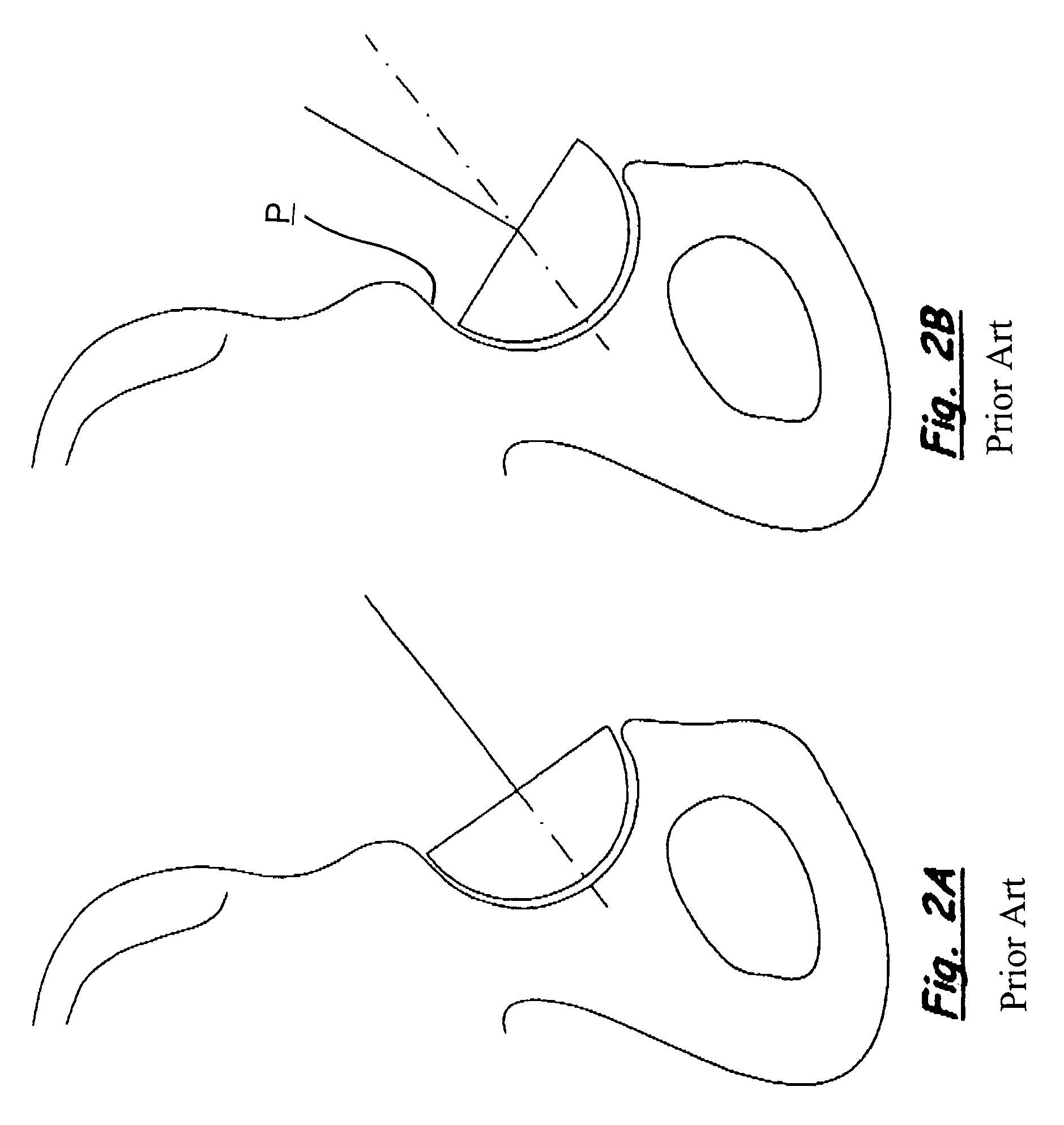
[0082]FIGS. 1A and B, and 2A and B illustrate prior art surgical techniques for hip arthroplasty. FIGS. 3-15C illustrate one embodiment of the invented reaming device and pieces-parts thereof. FIGS. 16A-E, and 17A and B schematically illustrate the preferred expansion structure and methods of the embodiment of FIGS. 3-15C, and FIGS. 18A and 18B schematically illustrate an embodiment such as that is FIGS. 3-15C in ...


PUM


Abstract

An expanding reamer prepares an acetabulum for a prosthetic component during hip arthroplasty. One or more blades expand in directions non-parallel to the plane of the respective blades and form an effective cutting sphere preferably greater-than-180-degrees for greater flexibility in placement of the reamer shaft relative to the center of axis of the acetabulum. Two parallel blades may move out away from each other and from the reamer rotational axis, staying parallel to each other to become more distanced, but still parallel, segments of a larger cuffing sphere. Or, two blades may start generally parallel to each other and to the rotational axis of the device, but pivot out from each other in directions generally perpendicular to their respective blade planes, again becoming more distanced, but not parallel, segments of a larger cuffing sphere.

Description

[0001]This application claims priority of U.S. application Ser. No. 11 / 137,123, filed May 24, 2005, and also claims priority of and incorporates by this reference U.S. application Ser. No. 60 / 749,968, filed Dec. 15, 2005.BACKGROUND OF THE INVENTION[0002]1. Field of the Invention[0003]The present invention relates generally to a reaming device and, more particularly, to an expandable reaming device that may be used for reaming an acetabulum in preparation for implanting a prosthetic component, such as an acetabular cup or socket during a hip arthroplasty.[0004]2. Related Art[0005]The hip joint is a ball-and-socket joint formed by the articulation of the rounded, convex surface of the head of the femur with the cuplike acetabulum on the pelvis. In a healthy hip joint, the head of the femur and the acetabulum are lined by surface cartilage; the entire joint is surrounded by a capsule which has a thin lining of synovial cells that produce a thin layer of lubrication film called synovial...

Claims


Application Information

Patent Timeline
Patent Type & Authority Patents(United States)
IPC IPC(8): A61B17/00
CPCA61B17/1666A61B17/00234A61B17/1617
Inventor BOTIMER, GARY
Owner BOTIMER GARY
Why Eureka
Try Eureka