
System and method for providing a graft in a vascular environment

a vascular environment and system technology, applied in the field of vascular procedures, can solve the problems of unsatisfactory current dialysis grafts, setbacks to patients, particularly troublesome issues remained in the field of kidney dialysis, etc., and achieve the effect of minimal stenosis, optimal patency, and improved patency

Inactive Publication Date: 2010-05-25
GRAFTECH INT HLDG INC
View PDF90 Cites 41 Cited by
  • Summary
  • Abstract
  • Description
  • Claims
  • Application Information

AI Technical Summary

Benefits of technology

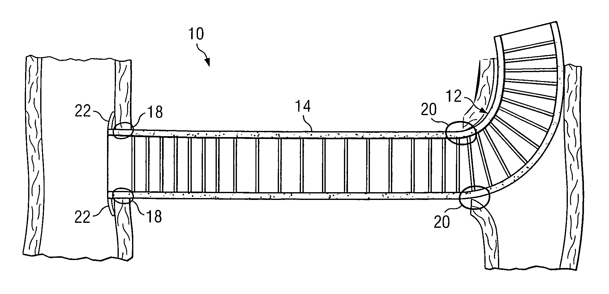
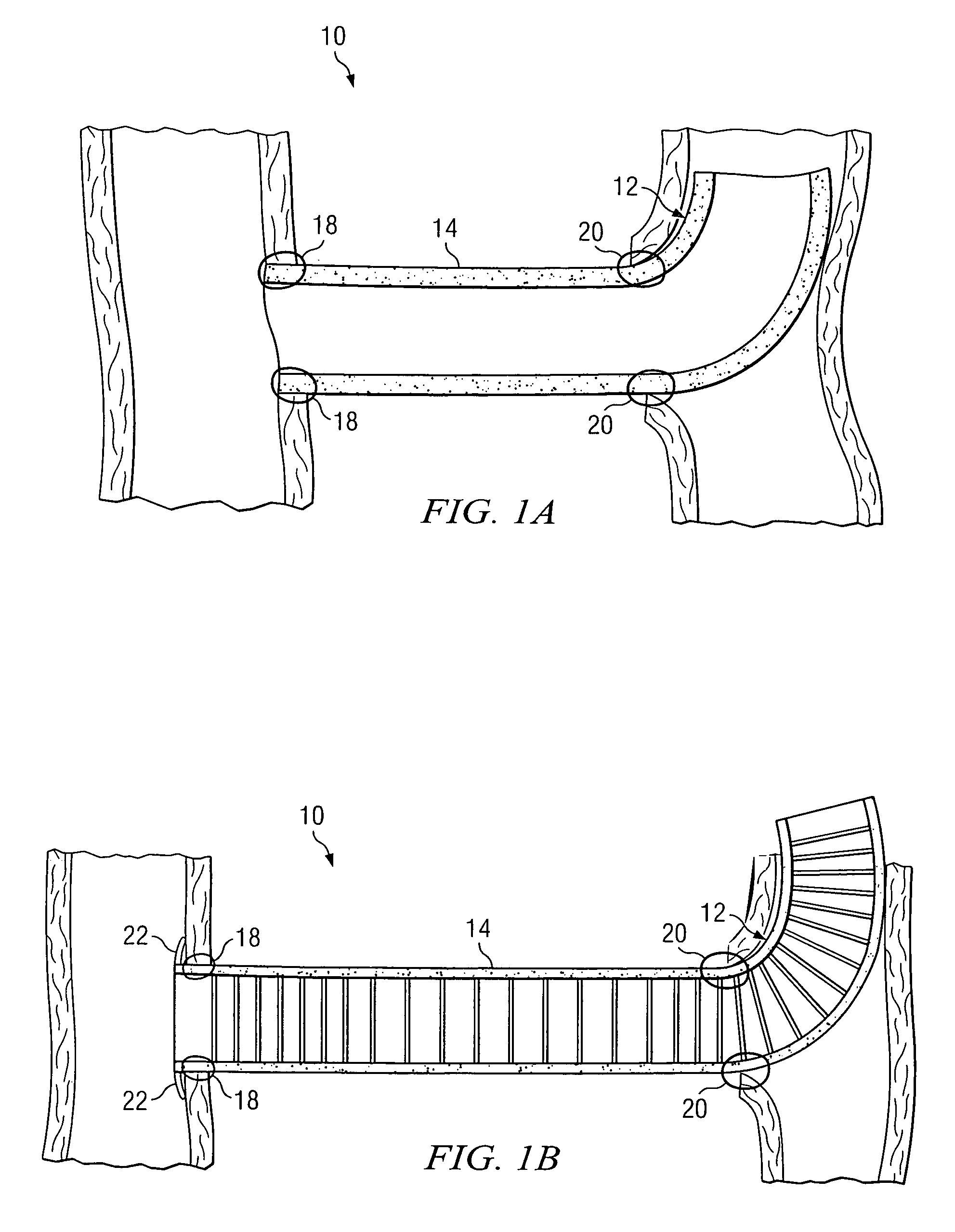
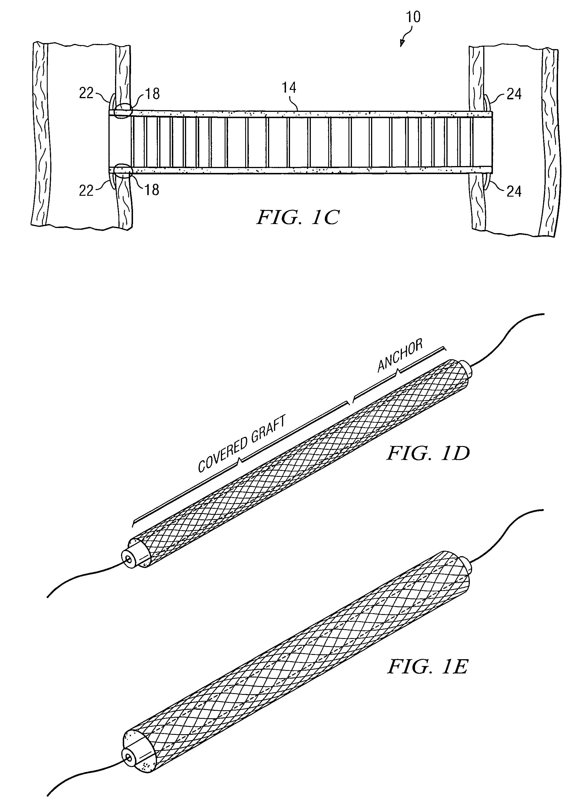
"The present invention provides an improved process for achieving superior flow, minimal stenosis, and optimal patency in a given vascular environment. A device, system, and method for facilitating optimal connections are provided that substantially eliminate or greatly reduce disadvantages and problems associated with conventional vascular devices, approaches, and strategies. The graft includes a hemodynamic profile that reduces scarring or occlusion-type complications that would otherwise arise. The graft offers a unique anchoring system that is stable and not prone to subsequent intimal hyperplasia. The graft structure can be leveraged to deliver drugs locally through various suitable elements. The architecture of the present invention can provide a new graft solution with significantly higher long-term patency rates."

Problems solved by technology

However, despite vast advancements in many vascular procedures and medical devices, one particularly troublesome issue has remained in the field of kidney dialysis.
Concisely stated, current dialysis grafts are simply not ideal for a multitude of reasons.
These grafts can cause setbacks to the patient due to poor instrument design, adverse reactions from the patient's body, and higher costs for all individuals involved.
Accordingly, the ability to properly address vascular issues involving conduits within a suffering patient presents a significant challenge for device manufacturers, physicians, and surgeons alike.

Method used


Image

  • System and method for providing a graft in a vascular environment
  • System and method for providing a graft in a vascular environment
  • System and method for providing a graft in a vascular environment

Examples


Embodiment Construction

[0026]For purposes of teaching and discussion, it is useful to provide some overview as to the way in which the following invention operates. The following foundational information may be viewed as a basis from which the present invention may be properly explained. Such information is offered earnestly for purposes of explanation only and, accordingly, should not be construed in any way to limit the broad scope of the present invention, its potential applications, and the appended claims.

[0027]For patients with end stage renal disease (ESRD), dialysis helps to remove waste, to balance certain chemicals in the blood, to remove excess fluid, and to control blood pressure. The survival of patients with ESRD is dependent on dialysis. There are two modalities of dialysis: hemodialysis and peritoneal dialysis, the former being the most common modality. In order to perform a hemodialysis procedure, a large vascular access is required. There are several methods of access available, several ...


PUM


Abstract

An apparatus is provided that includes a graft for coupling two vascular conduits within a patient. The graft includes: 1) an anchor system that forms an arc at one end of the conduits; and 2) a body element coupled to the anchor system. The anchor system comprises a biodegradable stent. In particular embodiments, portions of the graft are either self-expandable or balloon-expandable. In still other embodiments, anchor system includes NITINOL and the anchor system is substantially self-sealing at one end of the conduits. In one embodiment, the body element comprises polytetrafluoroethylene (PTFE) or expanded polytetrafluoroethylene (EPTFE). In yet other embodiments, the body element includes either a gelatinous or an elastomeric coating disposed on its surface.

Description

TECHNICAL FIELD OF THE INVENTION[0001]This invention relates in general to vascular procedures and, more particularly, to a process, a system, and a method for providing a graft in a vascular environment.BACKGROUND OF THE INVENTION[0002]The treatment of vascular diseases has grown exponentially in terms of sophistication and diversity. Procedures involving items such as stents or balloons are virtually routine in many health-care practices. However, despite vast advancements in many vascular procedures and medical devices, one particularly troublesome issue has remained in the field of kidney dialysis.[0003]The number of patients requiring hemodialysis treatment grows at an alarming rate. Because patients generally require treatment until death or until kidney transplantation, the projection for the number of future hemodialysis procedures increases with each new group of patients.[0004]Augmenting this problem is the prevalence of diabetes, which contributes directly to the number o...

Claims


Application Information

Patent Timeline
Patent Type & Authority Patents(United States)
IPC IPC(8): A61F2/06
CPCA61B17/11A61F2/07A61B2017/1107A61F2002/075A61F2/90A61B2017/1135
Inventor ANWAR, AZAMFEGHALI, GEORGES A.JOHNSON, KENNETH B.
Owner GRAFTECH INT HLDG INC
Learn More