Articulating implant system

a technology of articulating implants and implants, which is applied in the field of articulating implant systems, can solve the problems of fracture of the distal radius, difficult treatment of distal radius fractures, twisting force and compressing force on the forearm, etc., and achieves the elimination of the risk of component separation and the versatility of suture attachment.

Inactive Publication Date: 2010-05-25
WRIGHT MEDICAL TECH
View PDF11 Cites 80 Cited by
  • Summary
  • Abstract
  • Description
  • Claims
  • Application Information

AI Technical Summary

Benefits of technology

[0027]The articulating implant system allows for attachment of tissues near a surface or location of an articulating component without attaching the suture to that component. This allows independent rotation and orientation of the articulating component, a head in a modular ulnar implant system, with respect to the tissue suture attachment. Forces or constraints of the tissue attachment do not affect the orientation or behavior of the articulating component. The implant also allows for more versatility of the suture attachment by not being constrained to the non-articulating area of the articulating component.
[0028]In the case of a typical ulnar implant, there is risk of component separation

Problems solved by technology

Inherent bony instability, soft tissue damage, and frequent associated injuries make the distal radius fractures very difficult to treat.
When a person falls on an outstretched hand, the hand suddenly becomes rigid, and the momentum from the fall will cause both a twisting force and a compressing force on the forearm.
In children, and in older adults, such a fall is likely to result in a fracture of the radius.
Distal radius fractures may also result from direct trauma such as might occur during an auto accident.
Such a break may be extremely painful and produces a deformity that is easily seen.
In these cases, there is a significant risk of infection.
If the bones are seriously displaced, however, or if there is damage that needs to be repaired, surgery may be needed and the bones may need to be held together with pins or wire.
Closed treatment methods including casting, pins and plaster, and external fixation have frequently yielded unsatisfactory results.
With distal radial fractures, muscles may gradually weaken from lack of use during bone healing.
Fracture or dislocation involving the distal radioulnar joint often results in a loss of forearm rotation related to either instab

Method used


Image

  • Articulating implant system
  • Articulating implant system
  • Articulating implant system

Examples


Embodiment Construction

[0032]The present invention is directed to an articulating implant system for fixation to a bone. The implant system comprises two components: a fixation component and an articulating component.

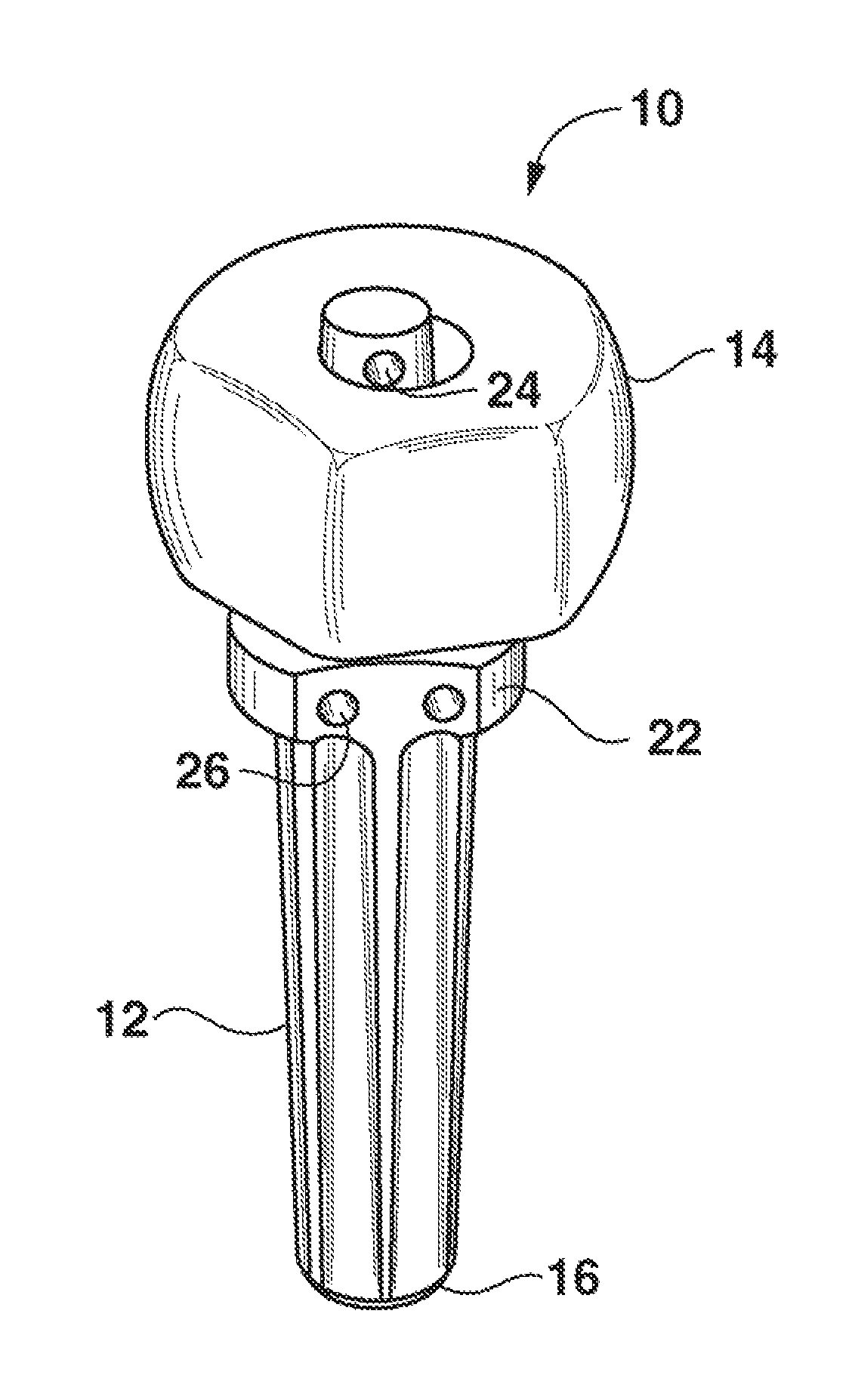
[0033]FIG. 1 illustrates a modular ulnar implant 10 in accordance with the articulating implant system of the present invention. The implant 10 is intended to be an anatomical replacement for the distal ulna after its resection. The modular ulnar implant 10 includes a fixation component and an articulating component. Specifically, the fixation component is a stem 12 and the articulating component is a head 14. Preferably, the stem 12 attaches to the head 14 via a morse taper.

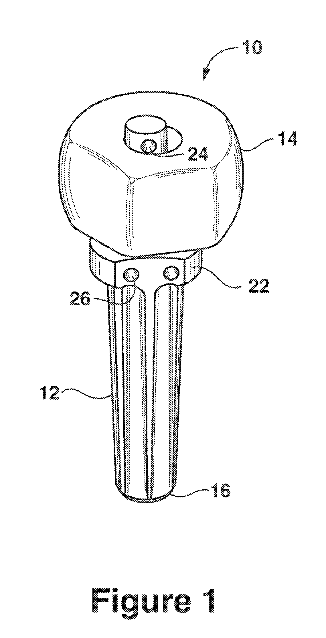
[0034]With particular reference to FIG. 1, the stem 12, or fixation component, is elongated and formed with first and second ends, 16 and 18. The first stem end 16 is configured for fixation to a bone, specifically, for insertion into the intramedullary canal of the distal ulna to thereby anchor the modular ulnar implant ...


PUM


Abstract

An articulating implant system is provided for fixation to a bone. The articulating implant system includes a fixation component for fixation to the bone and an articulating member for articulating against bone or cartilage. Specifically, a modular ulnar implant is provided in accordance with the articulating implant system of the present invention wherein the fixation component is a stem for insertion into the intramedullary canal of the distal ulna and the articulating member is a head for articulating with the radial sigmoid notch.

Description

RELATED APPLICATIONS[0001]This application claims priority to U.S. Provisional Patent Application Ser. No. 60 / 445,474, filed Feb. 5, 2003.FIELD OF THE INVENTION[0002]The present invention relates to an articulating implant system for fixation to a bone. Specifically, the present invention provides an articulating implant system for replacing the distal ulna.BACKGROUND OF THE INVENTION[0003]Both the proximal and distal radioulnar joints are synovial joints. The proximal joint lies between the head of the radius and the radial notch of the ulna. The distal radioulnar joint is separated from the wrist by an articular disc that extends from the base of the ulnar styloid process to the radius.[0004]The distal radioulnar joint is a pivot-joint formed between the head of the ulna and the ulnar notch on the lower end of the radius. The articular surfaces are connected together by the volar radioulnar ligament, the dorsal radioulnar ligament, and the articular disk. The volar radioulnar liga...

Claims


Application Information

Patent Timeline
IPC IPC(8): A61F2/42A61B17/06A61F2/00A61F2/30A61F2/46
CPCA61F2/4261A61B17/06166A61F2230/0065A61F2/4606A61F2/4637A61F2/4684A61F2002/30156A61F2002/302A61F2002/30332A61F2002/30574A61F2002/30604A61F2002/30691A61F2002/30784A61F2002/30827A61F2002/30878A61F2002/4269A61F2002/4631A61F2002/4681A61F2220/0033A61F2230/0023A61F2/30767
Inventor HANSON, SHAUNKING, GRAHAM J. W.PATTERSON, STUART D.TAYLOR, ALANJOHNSON, JAMES A.
Owner WRIGHT MEDICAL TECH
Why Eureka
Try Eureka