Magnetic disk and manufacturing method thereof

a magnetic disk and manufacturing method technology, applied in the field of magnetic disks, can solve the problems of fly stiction phenomenon, lubrication layer quality change, and remarkable problems, and achieve the effect of efficient manufacturing such a magnetic disk and excellent safety

Inactive Publication Date: 2010-05-25
WD MEDIA SINGAPORE PTE
View PDF9 Cites 73 Cited by
  • Summary
  • Abstract
  • Description
  • Claims
  • Application Information

AI Technical Summary

Benefits of technology

[0014]It is therefore an object of this invention to provide a magnetic disk that can prevent a fly stiction trouble, a corrosion failure, and so on to suppress a malfunction and is thus excellent in safety even when a magnetic head performs a flying operation at a flying height of, for example, 10 nm or less and, in particular, the magnetic disk that is suitable for an HDD of the LUL system.
[0015]It is another object of this invention to provide a method of efficiently manufacturing the magnetic disk.

Problems solved by technology

Further, interaction occurs between the adsorbed gas and a lubricant of a lubrication layer so that the lubrication layer is liable to change in quality.
Such problems are becoming remarkable particularly following a reduction in flying height of a magnetic head.
If this transfer state exceeds a certain level, a trouble called a fly stiction phenomenon and a corrosion failure occur.
The fly stiction is a trouble where the flying posture and height of the magnetic recording head go out of order during its flying operation and irregular changes in reproduction output occur frequently.
According to circumstances, the magnetic recording head is brought into contact with the magnetic recording medium to crash during the flying operation, thereby destroying the magnetic disk.
This fly stiction often occurs without a premonitory sign and is one of troubles that are difficult to control.
Therefore, particularly in the LUL system, the lubricant and the organic compound etc. tend to be transferred and deposited on the magnetic recording head so that the fly stiction is liable to occur and a head element portion is liable to be corroded.
Following it, there has been arising a problem about flying stability of heads.
As a result, a problem of the fly stiction has occurred frequently.

Method used


Image

  • Magnetic disk and manufacturing method thereof
  • Magnetic disk and manufacturing method thereof
  • Magnetic disk and manufacturing method thereof

Examples


example 1

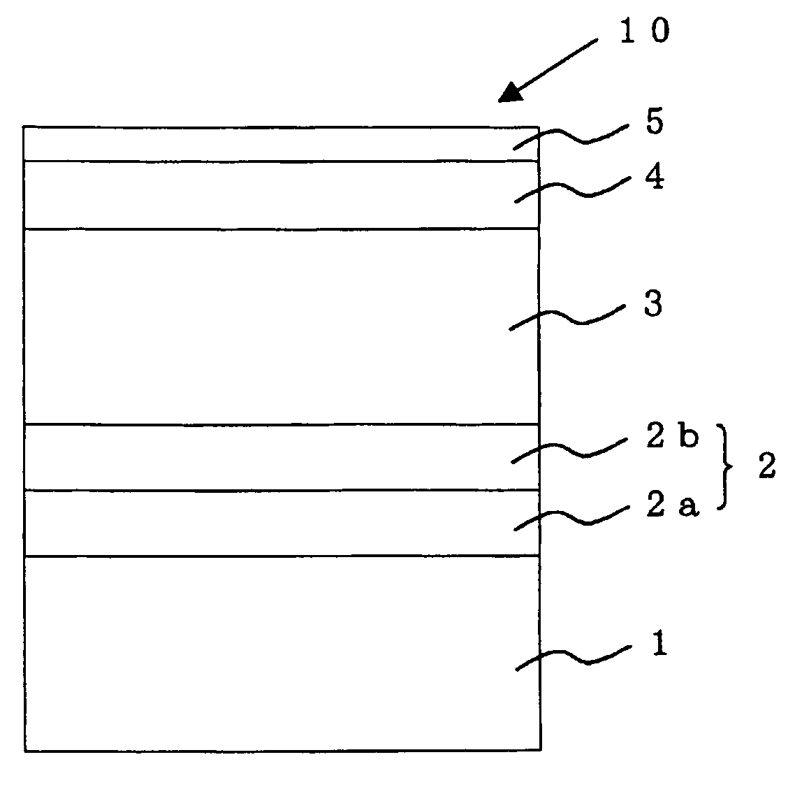
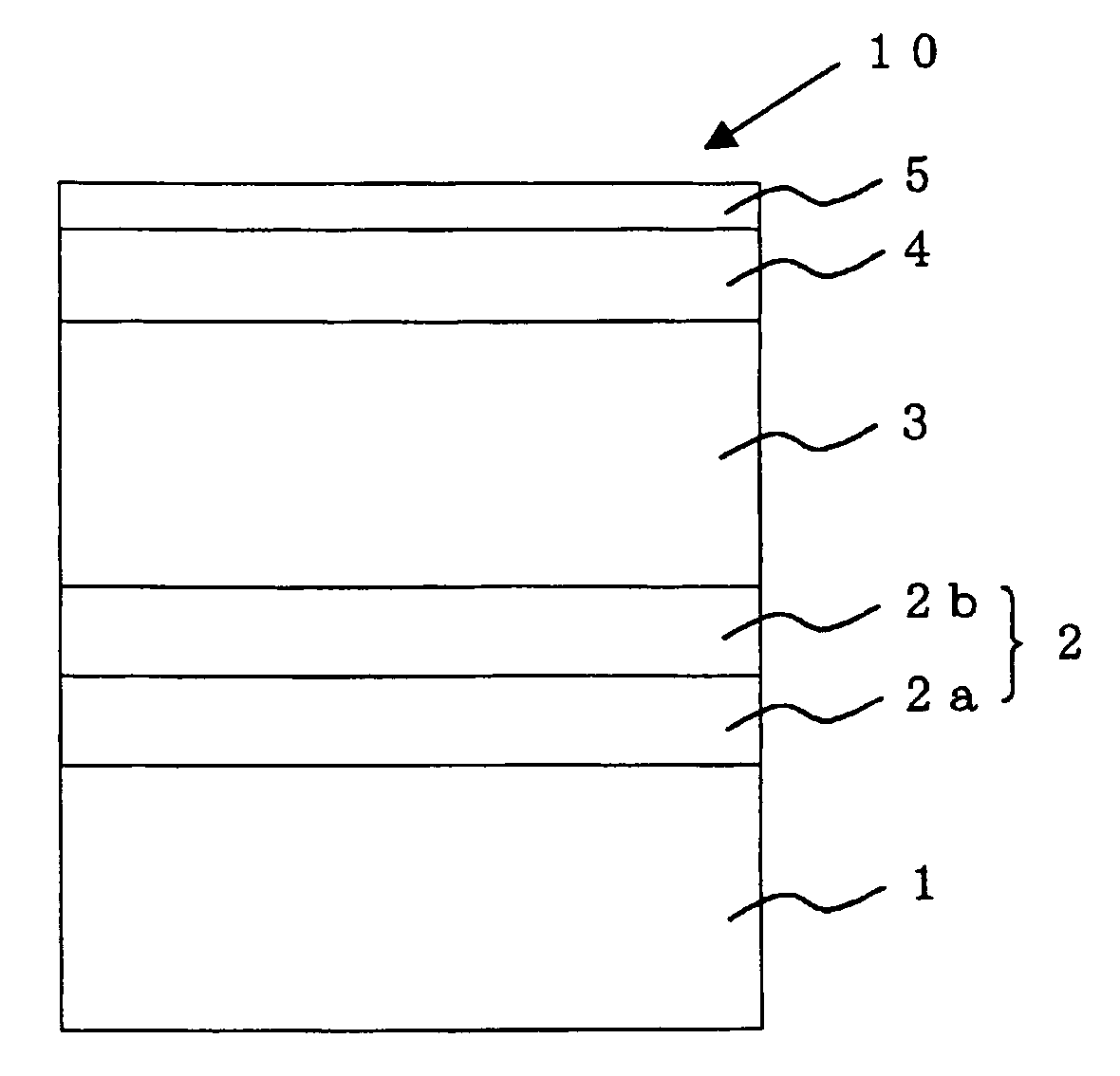
[0101]A magnetic disk 10 for the LUL system having a structure shown in FIG. 1 was manufactured.

[0102]First, aluminosilicate glass was formed into a disk shape to obtain a glass disk. By applying grinding, precision polishing, end-face polishing, precision cleaning, and chemical strengthening to the obtained glass disk, a flat, smooth, and high-rigidity glass substrate 1 for a magnetic disk was obtained. This glass substrate 1 was a 2.5-inch magnetic disk substrate having a diameter of 65 mm, an inner diameter of 20 mm, and a disk thickness of 0.635 mm.

[0103]Here, observing the surface roughness of the obtained glass substrate 1 by the use of an AFM (Atomic Force Microscope), it was confirmed to be a smooth surface having Rmax of 3.96 nm and Ra of 0.36 nm.

[0104]Then, by the use of a static opposed type film-forming apparatus, a seed layer 2a, an underlayer 2b, and a magnetic layer 3 were formed on the glass substrate 1 in this order by DC magnetron sputtering. Specifically, first, u...

examples 2 to 4

[0151]In the manufacture of a magnetic disk of Example 1, the processing was performed like in Example 1 except that the treatment time by HFE (hydrofluoroether) was changed as shown in Table 1. The results are shown in Table 1.

[0152]

TABLE 1ComparativeExample 1Example 1Example 2Example 3Example 4Hydro-yesnoyesyesyesfluoro-(vapor(vapor(vapor(vaporetherdeposition)deposition)deposition)deposition)TreatmentTreatment60 seconds—102030TimesecondssecondssecondsγSd (mN / m)15.0217.6617.4716.0315.87γSp (mN / m)0.022.231.140.550.49γSh (mN / m)4.079.522.852.462.25γS (mN / m)19.1129.4121.4519.0418.61γSLW (mN / m)15.0217.6617.4716.0315.87γS− (mN / m)5.0710.454.243.853.42γS+ (mN / m)0.882.850.920.640.66γS (mN / m)19.2528.5721.4219.1818.88Critical Surface14.9617.1216.9315.5515.42Tension [γc] (mN / m)Fly Stiction Test98%70%81%88%93%(Passing Rate)LUL (Load Unload)durablefailed atdurabledurabledurableDurability Test1,000,000600,0001,000,0001,000,0001,000,000(Number of Durabletimes ortimestimes ortimes ortimes orTimes)m...


PUM

PropertyMeasurementUnit
surface free energy γSaaaaaaaaaa

Abstract

In a magnetic disk having a magnetic layer, a protection layer, and a lubrication layer formed on a substrate in this order, a surface free energy γS of a surface of the magnetic disk derived by an extended Fowkes equation is greater than 0 and no greater than 24 mN / m. γSd (dispersion force component of surface free energy) forming the surface free energy γS is greater than 0 and no greater than 17 mN / m, γSp (dipole component of surface free energy) forming the surface free energy γS is greater than 0 and no greater than 1 mN / m, and γSh (hydrogen bonding force component of surface free energy) forming the surface free energy γS is greater than 0 and no greater than 6 mN / m.

Description

[0001]This application claims priority to prior Japanese Patent Application No. 2004-30295, the disclosure of which is incorporated herein by reference.BACKGROUND OF THE INVENTION[0002]This invention relates to a magnetic disk for use in a magnetic recording device (HDD, Hard Disk Drive) or the like and a manufacturing method thereof. More specifically, this invention relates to a magnetic disk that can prevent a fly stiction trouble, a corrosion failure, and so on to suppress a malfunction and is thus excellent in safety even when a magnetic head performs a flying operation at a flying height of, for example, 10 nm or less, and a manufacturing method of the magnetic disk.[0003]An LUL (Load Unload) system capable of higher recording capacity has started to be employed in HDDs (Hard Disk Drives) in recent years. In the LUL system, upon halting, a magnetic recording head is retreated to a slope bed called a ramp located outside a magnetic disk while, upon starting, the magnetic record...

Claims


Application Information

Patent Timeline
Patent Type & Authority Patents(United States)
IPC IPC(8): G11B5/66G11B5/64G11B5/72G11B5/725G11B5/84
CPCG11B5/64G11B5/8408Y10T29/49702G11B5/72G11B5/7266
Inventor ISHIYAMA, MASAFUMI
Owner WD MEDIA SINGAPORE PTE
Why Eureka
Try Eureka