Brightness enhancement with directional wavelength conversion

a technology of directional wavelength conversion and brightness enhancement, which is applied in the field of illumination systems, can solve the problems of reducing the wavelength conversion efficiency of standard led arrays, unable to provide sufficient brightness, and even damage, and achieves the effect of efficient light collection and higher light brightness

Active Publication Date: 2010-06-01
APPOTRONICS CORP LTD
View PDF3 Cites 6 Cited by
  • Summary
  • Abstract
  • Description
  • Claims
  • Application Information

AI Technical Summary

Benefits of technology

[0007]There is, therefore, a need for the ability to efficiently collect the light from multiple LEDs, generating light with other wavelength converting material physically far away from the LED chips and to construct a light system with higher light brightness compared to an individual LED.
[0009]In an embodiment of the present invention, an LED based illumination system with enhanced brightness includes a light source such as LEDs, light couplers for efficiently collecting and collimating the light from LEDs, wavelength selective filters, light concentrators that focus the collimated light, a cavity constructed by layers of wavelength converting material such as phosphorescent materials located the focus planes of the light concentrators. The LEDs provide the light of a first wavelength (the term “wavelength” is used in this disclosure for convenience, but it should be understood to refer to a wavelength range unless otherwise clear from the context). The light couplers efficiently collect and collimate the light from the LED. Each coupler includes a light tunnel portion and a compound parabolic reflecting surface portion. Exiting LED light that is substantially perpendicular to the LED chip surface is directly applied to the compound parabolic reflector and is collimated. The LED light that is substantially parallel to LED chip surface strikes the light tunnel portion and is guided into the parabolic reflecting portion through one or multiple reflections and is also collimated. A wavelength selective filter is placed at the output of the collimated light of the first wavelength but before the light concentrator that focus the collimated light. At the focus of the concentrator is the layer of the cavity made of a wavelength conversion material. The layer of the wavelength conversion material forms a cavity that passes the focused light of the first wavelength. There is at least one aperture on the cavity to allow light at both the first wavelength and a second wavelength pass. The light at the first wavelength passing through the filters interacts with the wavelength converting material and generates the light of the second wavelength that is different from the first wavelength. The wavelength selective filters reflect the light with the second wavelength and prevent the light with second wavelength from going back to the light couplers and then back to the light source such as LEDs. Therefore the light of the second wavelength can only propagate in the forward direction and is trapped and cycles inside the cavity until it exits the cavity through an aperture on the cavity. Since the side surfaces of the cavity are form from the focus surface and the aperture is significantly smaller than 50% of total cavity area, the brightness of the output light is enhanced.
[0010]In another embodiment of the present invention, an LED based illumination system with enhanced brightness includes a cavity constructed by a layer of wavelength converting material such as phosphorescent material, light concentrators that focus the collimated LED light, wavelength selective filters, and optical fibers or fiber bundles that transport the collimated light from LEDs, and light couplers for efficiently collecting and collimating light from LEDs. The light couplers efficiently collect and collimate the light of the first wavelength from the LED. Each coupler provides a light tunnel portion and a compound parabolic reflecting surface portion. Exiting LED light that is substantially perpendicular to the LED chip surface is directly applied to the compound parabolic reflector and is collimated. LED light that is substantially parallel to the LED chip surface strikes the light tunnel portion and is guided into the parabolic reflecting portion through one or multiple reflections and is also collimated. The collimated light of the first wavelength is then collected by an optical fiber. LED output from multiple fibers can be further combined through fiber bundling or fiber fusion. A wavelength selective filter is placed at the fiber output of the collimated light of first wavelength but before the light concentrator that focus the collimated light. At the focus of the concentrator is the layer of the cavity made of the wavelength conversion material. The light of the first wavelength passes through and interacts with the wavelength converting material that generates light of a second wavelength different from the first wavelength. The light of the second wavelength that travels back to the concentrator will be reflected back by the wavelength selective filters which prevent the light of the second wavelength from going back to the fiber and then back to the LED. Further improvement of brightness is obtained from the increase of the effective light conversion efficiency since the loss of light that go back to the light source is prevented, as well as the reduction of beam spot size by the concentrator. The light of the second wavelength from the light conversion material can only propagate in the forward direction as the collimated light of the first wavelength. The light of the second wavelength can directly exit the cavity or cycle inside the cavity until exiting the cavity through an aperture on the cavity. When the reflectivity of optical components is high enough (or the loss is low), there is no significant light loss. With an appropriate size of the aperture, the output light brightness is enhanced.

Problems solved by technology

Therefore, a standard LED array has difficulties in providing sufficient brightness for many applications requiring directional beam such as projection light sources and automotive headlamps.
Furthermore, as the LED chip temperature increase due to the increase of driving current, the phosphorescent material directly contacting the LED chip may reduce its wavelength converting efficiency and can even be damaged by the heat.

Method used


Image

  • Brightness enhancement with directional wavelength conversion
  • Brightness enhancement with directional wavelength conversion
  • Brightness enhancement with directional wavelength conversion

Examples


Embodiment Construction

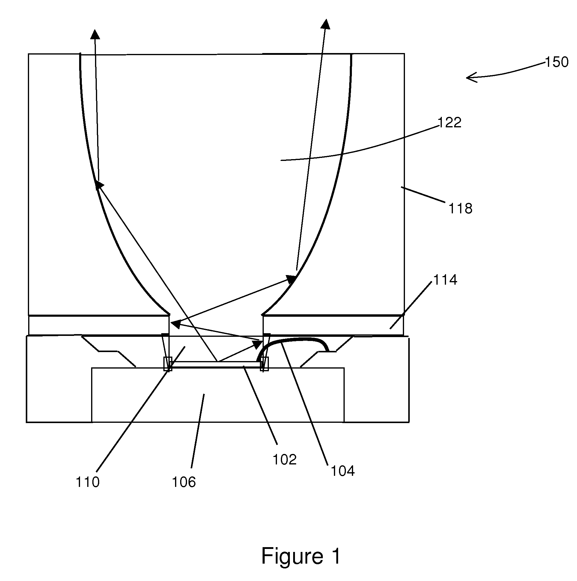
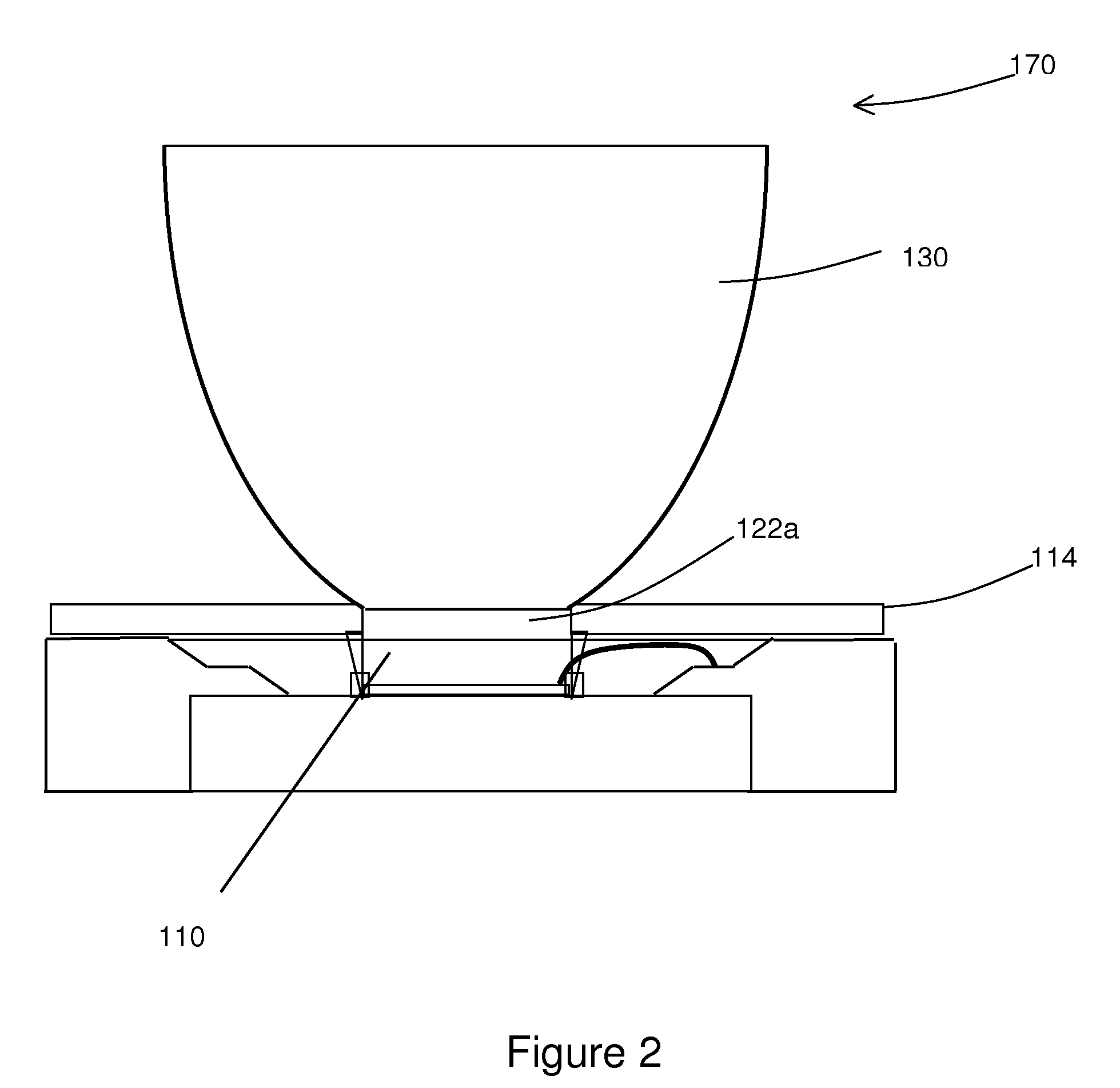
[0023]FIG. 1 illustrates one embodiment of the invention which uses a light coupler for efficient colleting and collimating of light from a light source such as an LED. The LED chip 102 sits on a heat sink 106 and is covered by a transparent material 110 and emits a light of a first wavelength range. The LED 102 is driven by electrical current supplied by bonding wires 104. The light coupler has one portion which is a light tunnel 114 and another portion which has a compound parabolic reflective surface 118. The compound parabolic portion 118 is formed by molded solid transparent part. The reflection surface of the coupler has a high reflectivity (greater than 80%) for the first wavelength. The reflective surface can be coated with metal (such as Al or silver) or multi-layer dielectric coating, or the combination of both. To further improve the light escaping efficiency, the space enclosed by the light coupler can be filled with a transparent material 122 with a refractive index mat...


PUM


Abstract

An LED based illumination system with enhanced brightness is described. The system includes one or more light sources such as LEDs, one or more light couplers for efficiently collecting and collimating the light from the light sources, one or more wavelength selective filters, one or more light concentrators that focus the collimated light, and a cavity made of a layer of wavelength converting material such as a phosphorescent material located at the focus planes of the light concentrators. Each light coupler includes a light tunnel portion and a compound parabolic reflecting portion, and effectively collects and collimates light emitted by the LED in all directions. The wavelength selective filters pass the collimated light from the light sources and reflect light of a second wavelength generated by the phosphorescent material. The lights of both wavelengths exit the light cycling cavity through an aperture.

Description

[0001]This application claims priority from U.S. Provisional Patent Application No. 60 / 834,437, filed Jul. 31, 2006, which is herein incorporated by reference in its entirety.BACKGROUND OF THE INVENTION[0002]1. Field of the Invention[0003]The present invention generally relates to illumination system using a light emitting diode array and wavelength conversion.[0004]2. Description of the Related Art[0005]Solid-state illumination devices such as light emitting diodes have many benefits as compared with traditional illumination sources. Light emitting diodes (LEDs) have long lifetime, high energy-efficiency, pure color characteristic, good modulation performance, and shock resistant. White-light generation using blue or UV LED to excite phosphorescent materials provides a great potential for replacing traditional light source such as incandescent lamp and even fluorescent lamp.[0006]Although multiple LEDs can linearly scale up total output lumen, the average brightness of a simple LED...

Claims


Application Information

Patent Timeline
Patent Type & Authority Patents(United States)
IPC IPC(8): F21V7/04F21S4/00
CPCG02B6/4206G02B6/4298G02F2001/133614G02F1/133614
Inventor XU, LI
Owner APPOTRONICS CORP LTD
Why Eureka
Try Eureka