
Tools for 3D mesh and texture manipulation

a 3d mesh and texture technology, applied in the field of tools for 3d mesh and texture manipulation, can solve the problems of increasing computation time, reducing the overall accuracy of the model, and not being well-suited to the construction of the mesh based on an irregular set of data points, so as to reduce the amount of rendering calculations, reduce memory requirements, and facilitate manipulation and adjustment. the effect of intuitive and efficien

Inactive Publication Date: 2010-06-01
SIZMEK TECH
View PDF6 Cites 76 Cited by
  • Summary
  • Abstract
  • Description
  • Claims
  • Application Information

AI Technical Summary

Benefits of technology

[0012]The present invention provides techniques that may be used individually or in combination to allow more efficient and intuitive manipulation and adjustment of 3D meshes as well as reduce the memory requirements and the amount of rendering calculations that must be performed in real time.
[0013]One embodiment of the present invention provides an accurate translation of a freeform screen selection into a selection of faces and vertices on the mesh. Any new vertices and faces that are necessary to allow the selection on the mesh to accurately reflect the user's desired selection are calculated automatically without requiring painstaking manual additions by the user. The present invention accomplishes this by approximating the screen selection as a polygonal shape, projecting the 3D mesh onto the polygonal shape as a 2D triangulated mesh, adding new vertices and edges to those triangles bisected by the polygonal shape, and retriangulating the intersected triangles to form the necessary new faces.
[0015]Another embodiment of the present invention allows adjustments to the way in which textures are mapped onto the 3D mesh. When a coordinate of a texture is selected and dragged to a new location, the other coordinates in the texture are smoothly transformed to accommodate the move based on the distance the selected coordinate was moved, the distance the present coordinate was from the selected coordinate, and a weight function. This transformation is accomplished in 2D space rather than 3D space, thus reducing the amount of calculation required and making it possible for the user to see the results of the transformation as the selected coordinate is being dragged.
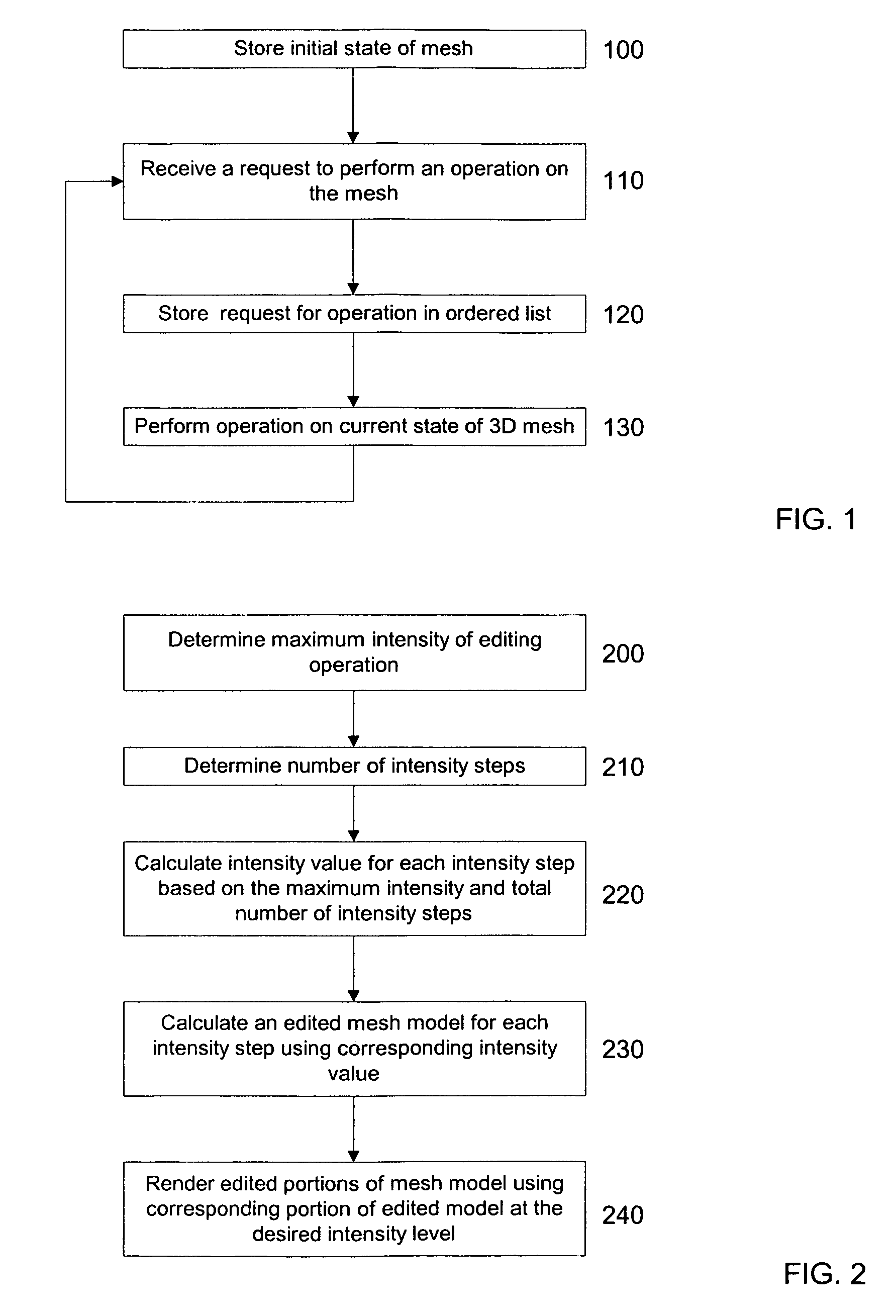
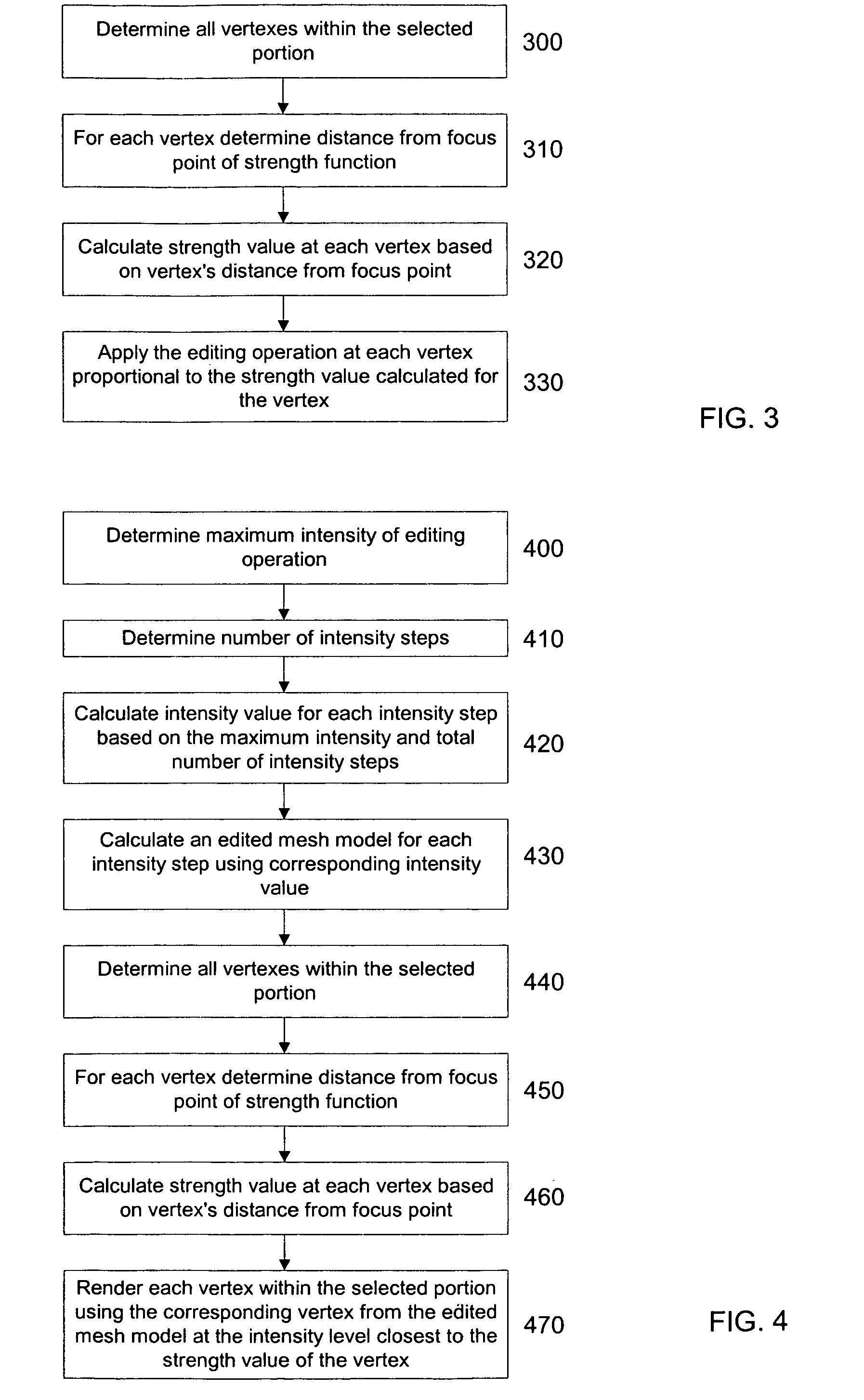
[0017]The present invention also includes embodiments that reduce the amount of real time calculations that must be performed in implementing the other embodiments. When an editing operation is anticipated, the present invention applies the editing operation to the mesh at successively greater strengths and stores the results of each application. When the editing operation is to be performed on all or part of the original mesh at a particular strength, the stored mesh (or part thereof) at the corresponding strength is substituted for the appropriate portion of the original mesh.
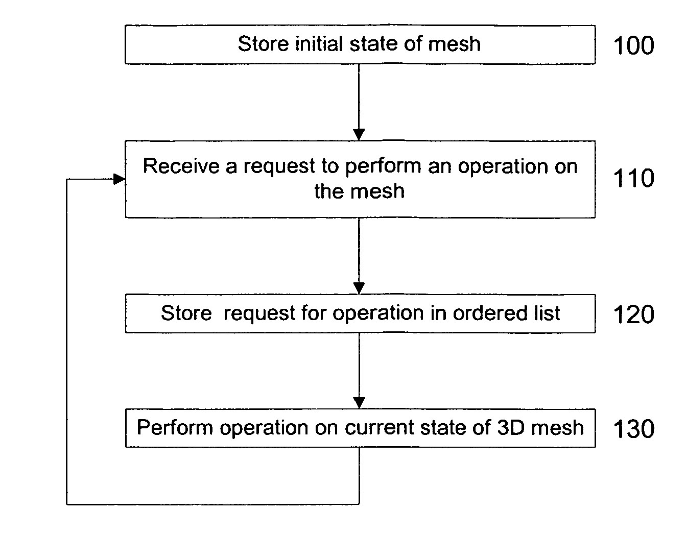
[0018]The present invention further includes embodiments that provide for storing the mesh in memory by storing an initial mesh with an ordered list of all operations performed on the mesh. This allows reversion to previous versions of the mesh to be accomplished more easily without requiring that an individual copy of the mesh be stored after each operation is performed on it.

Problems solved by technology

While gridded models provide regular, predictable structures, they are not well-suited for mesh constructions based on an irregular set of data points, such as those generated through laser scanning or silhouette capture of real world objects.
The need to interpolate an irregular set of data points into a regular grid structure increases computation time and decreases the overall accuracy of the model.
Many users have difficulty making these adjustments because they require manipulating a three dimensional object (i.e. the mesh model) in what is essentially a two dimensional space (i.e. the computer screen) using tools that generally move in only two dimensions (i.e. the mouse and cursor keys).
Other difficulties arise from the fact that mesh manipulation is limited to manipulating entire faces or vertices.
Adding vertices and faces can be very difficult if it has to be done manually, especially for a novice user.
However, real time 3D rendering requires that the computer system perform a tremendous number of calculations in a short period of time.
Users also frequently make changes to a mesh model, discard those changes as unwanted, and revert back to a prior version.
If the mesh model is of any significant size, the memory limitations of the computer may become taxed relatively quickly.

Method used


Image

  • Tools for 3D mesh and texture manipulation
  • Tools for 3D mesh and texture manipulation
  • Tools for 3D mesh and texture manipulation

Examples


Embodiment Construction

[0030]The present invention can be used in 3D modeling software on a variety of computing hardware such as personal computers based around Intel, AMD, Motorola, or Transmeta processors, or workstations such as those built by IBM or SGI, running any of a variety of operating systems such as Microsoft Windows, MacOS, Unix, Linux, or OS / 2. The software implementing the methods of the present invention can be developed in any suitable programming language, such as C, C++, or Java.

[0031]One embodiment of the present invention reduces the amount of memory that is required to maintain a record of prior versions of the 3D mesh as the editing process progresses. This record is typically used to allow the user the option of “undoing” any operations that have been performed that the user later decides are undesirable. However, storing a copy of the mesh after each editing operation is performed would quickly consume a large amount of memory especially if the mesh is sufficiently complex. In ac...


PUM


Abstract

Improvement of the performance, usability, and functionality of software for editing three dimensional computer models and textures is described. Editing operations are performed on the model in an ordered list to reduce the amount of memory required to maintain previous versions, and certain editing operations are precalculated to reduce the amount of real time calculation required. Improvements to usability and functionality are provided by more precisely selecting portions of a model for editing, allowing textures to be moved more easily on the model, and allowing better blending of the appearance of adjacent textures.

Description

[0001]This application claims the benefit of U.S. Provisional Application No. 60 / 192,506, entitled “System and Method of Three Dimensional Image Capture and Modeling”, filed Mar. 28, 2000.FIELD OF THE INVENTION[0002]The present invention is directed to tools for editing three dimensional (“3D”) mesh models and textures on a computer.BACKGROUND OF THE INVENTION[0003]There is increasing interest in the use of three-dimensional models of physical objects to improve productivity and innovation in fields such as digital imaging, computer animation, special effects in film, prototype imaging in product development, topography, reconstructive and plastic surgery, dentistry, architecture, industrial design, anthropology, milling and object production, biology, and internal medicine. In addition, with the recent explosion of the Internet and the World Wide Web, there is a demand for computer-generated 3D models for use on Web sites. Although 2D images currently predominate in the display and...

Claims


Application Information

Patent Timeline
IPC IPC(8): G09G5/00G06F19/00G06T17/20
CPCG06T17/205G06T17/20
Inventor PETROV, MICHAELMIGDAL, ALEXANDERLEBEDEV, ALEXEISHELYEKHOVA, VERONIKAPOLONSKIY, LEONIDABADJEV, VADIM
Owner SIZMEK TECH
Learn More