Method and installation for acousto-optic imaging

a technology of optical imaging and installation method, applied in the field of acoustical imaging methods and installations, can solve the problems of poor sensibility of the technique, loss of most of the signal, and camera too slow to detect interference signals

Inactive Publication Date: 2010-06-08
CENT NAT DE LA RECHERCHE SCI +1
View PDF5 Cites 12 Cited by
  • Summary
  • Abstract
  • Description
  • Claims
  • Application Information

AI Technical Summary

Benefits of technology

[0064]the installation also comprises a control device designed to cause said transducer to be displaced and / or the focal length of said transducer to be changed.

Problems solved by technology

However, this technique offers poor sensibility.
Such a detection is effective only for a very small geometric expanse, such that most of the signal is lost.
There is, however, a problem in that such a camera is too slow to detect an interference signal between the carrier and acousto-optic components of the signal wave, which has a high frequency, of the order of that of the acoustic wave (a few MHz, typically).
This technique is not, however, the best possible because, on the one hand, the measured signal includes a significant noise component due to the photons that are simply scattered having passed through an area of the object to be imaged that is not vibrating, and on the other hand, the reference component is relatively weak, because it passes through the scattering medium.
If a continuous part associated with the acoustically unmarked component can easily be eliminated during the detection, the amplitude and phase variations of the signal wave, which are reflected by the decorrelation of the speckle, often lead to a false signal called “speckle decorrelation noise”.
Living biological tissues, for which the acousto-optic imaging technique is required to be used, for example in screening for breast cancer, or other purposes, lead to a major speckle decorrelation noise.
There is therefore a lack of a method that can guarantee a good measurement sensitivity for biological tissues.

Method used


Image

  • Method and installation for acousto-optic imaging
  • Method and installation for acousto-optic imaging
  • Method and installation for acousto-optic imaging

Examples


Embodiment Construction

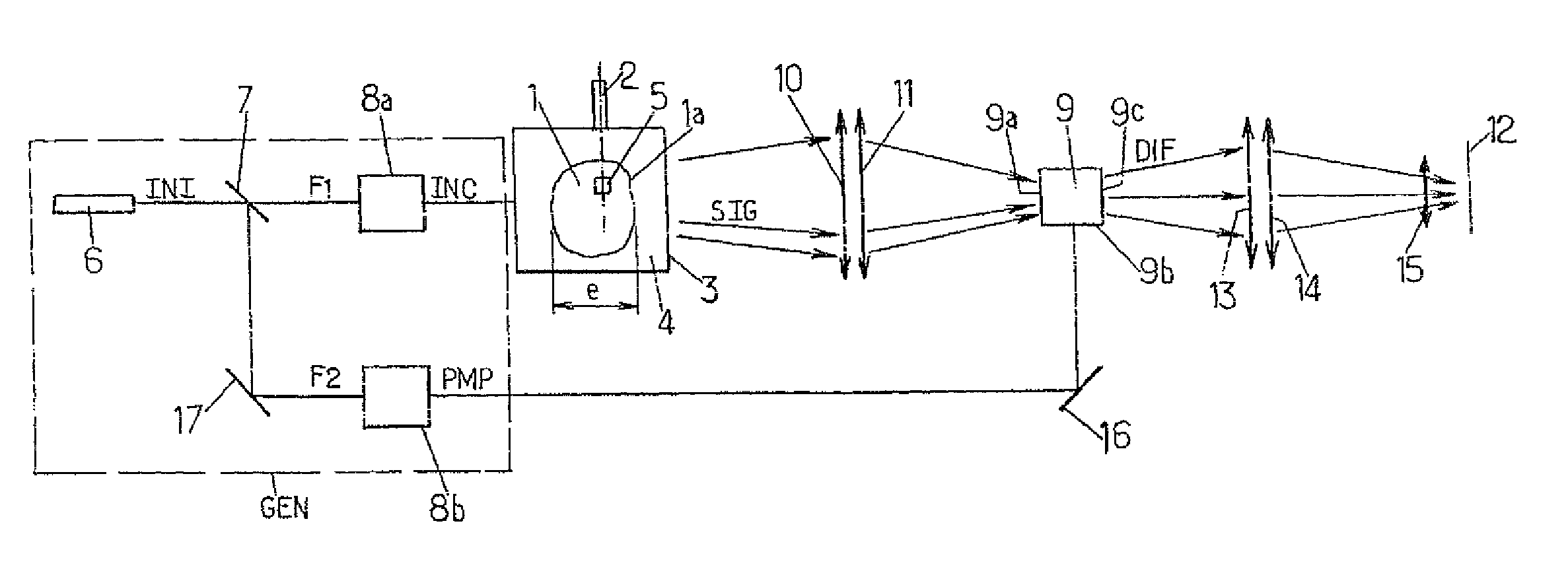
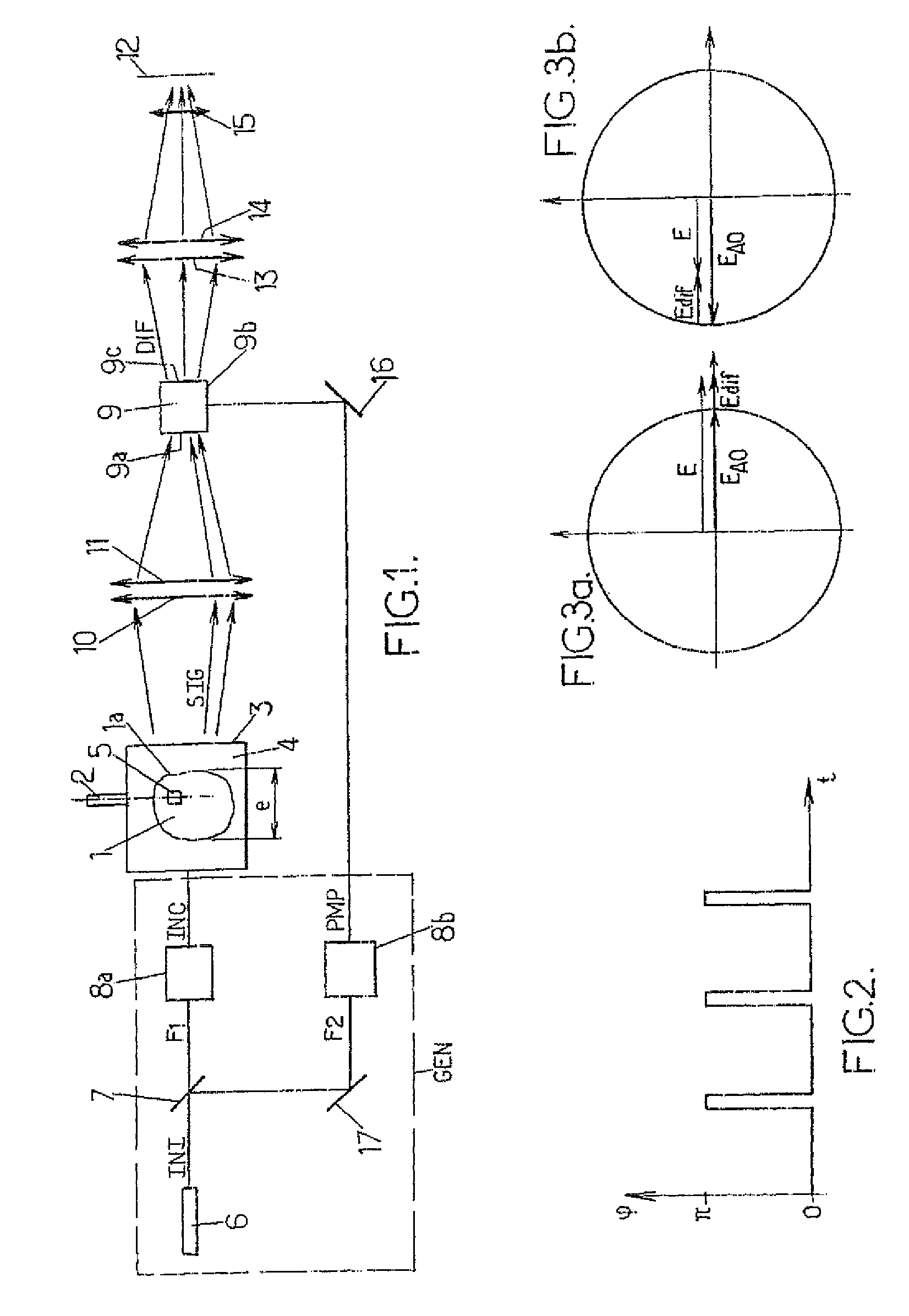
[0072]FIG. 1 diagrammatically represents an acousto-optic imaging installation that can be used in the context of the invention.

[0073]There is an object 1 to be imaged using said installation. This object is a scattering medium, typically of a thickness e of a few centimeters and can, for example, be a biological tissue, such as a part of the human or animal body, or other.

[0074]A piezo-electric transducer 2 is in acoustic contact with the object 1, either directly in contact or, for example, acoustically coupled to the object 1 by the immersion of the latter in a tank 3 filled with water 4. For example, a Panametrics piezo-electric transducer of diameter 37 mm with a spherical output face of radius 75 mm is used. The transducer vibrates the area of the object that is in line with it, and in particular the area 5 at the ultrasound acoustic frequency fa, such as for example 2 MHz. The piezo-electric transducer 2 is placed facing a given position of the surface of the object. The piez...


PUM

PropertyMeasurementUnit
radiusaaaaaaaaaa
poweraaaaaaaaaa
wavelengthaaaaaaaaaa

Abstract

This invention concerns an acousto-optic imaging method comprising a step which consists in engraving in a dynamic holographic material a complex index array resulting from the interference of the acousto-optic component of the signal wave and a pump wave of frequency equal to the frequency of the acousto-optic component.

Description

CROSS-REFERENCE TO RELATED APPLICATION[0001]This is the U S. National Phase of International Application No. PCT / FR2005 / 01446 filed 10 Jun. 2005, the entire disclosure of which is incorporated herein by referenceFIELD OF THE DISCLOSURE[0002]The present invention relates to acousto-optic imaging methods and installations.BACKGROUND OF THE DISCLOSURE[0003]More particularly, the invention relates to an acousto-optic imaging method.[0004]In this type of method, an object to be imaged is illuminated with a laser-type light source. Moreover, acoustic waves are propagated in the object by an ultrasound source. Information is obtained for an area of the object to be imaged by detecting a signal linked to the coupling properties between the light wave and the ultrasound wave which specifically makes the concerned area vibrate. In practice, when an ultrasound wave, of acoustic frequency fa passes through a scattering medium (such as, for example, a biological tissue, or other), it provokes a ...

Claims


Application Information

Patent Timeline
Patent Type & Authority Patents(United States)
IPC IPC(8): H04B11/00A61B5/00A61B8/08G01B9/02G01N21/49G01N29/06G01N29/24G03H1/00G03H1/04G03H3/00
CPCA61B5/0059A61B5/0097A61B8/0833G01N21/49G01N29/0663G03H1/00G01N29/2418A61B8/0825G03H2260/36G01N2291/0427G03H1/0406G03H2001/0268G03H2001/0463
Inventor GROSS, MICHELRAMAZ, FRANCOIS GEORGES GERARDFORGET, BENOIT CLAUDEROOSEN, GERALDDELAYE, PHILIPPEBOCCARA, ALBERT-CLAUDE
Owner CENT NAT DE LA RECHERCHE SCI
Why Eureka
Try Eureka