Organic electroluminescence device having input function and electronic apparatus

a technology of electroluminescence device and electronic apparatus, which is applied in the direction of discharge tube/lamp details, discharge tube luminescnet screen, instruments, etc., can solve the problems of touch-sensitive liquid crystal device of the related art described above having a technical, contact position detection error, and decrease in accuracy, so as to improve detection accuracy and reliability. , the effect of increasing performan

Active Publication Date: 2010-06-15
ELEMENT CAPITAL COMMERCIAL CO PTE LTD
View PDF11 Cites 25 Cited by
  • Summary
  • Abstract
  • Description
  • Claims
  • Application Information

AI Technical Summary

Benefits of technology

[0007]An advantage of some aspects of the invention is to provide an organic electroluminescence device that is capable of achieving noise-suppressed contact position detection with a high precision in a reliable manner. In addition, the invention further provides, advantageously, an electronic apparatus that is provided with such a high-performance organic electroluminescence device to offer reliable contact position detection with enhanced detection accuracy.
[0010]In the configuration of the organic electroluminescence device having an input function according to the first aspect of the invention described above, a touch panel configuration conforming to a capacitive sensing scheme is combined with the configuration of an organic electroluminescence device. With such a configuration, it is possible to reduce the adverse effects of a noise exerted onto the functioning of a first detection electrode and a second detection electrode. Therefore, it is possible to improve the accuracy in the detection of a touch panel user input. In addition, the organic electroluminescence device having an input function according to the first aspect of the invention described above is provided with the first detection electrode and the second detection electrode having detection axes orthogonal to each other. With such a configuration, it is possible to make a positional detection that is fully responsive to a touch contact input made along, for example, both the X direction and the Y direction. Therefore, it is possible to improve the reliability of touch panel contact detection. Thus, the organic electroluminescence device having an input function according to the first aspect of the invention described above ensures a high precision in the detection of a touch panel user input, thereby making it possible to offer a reliable touch-sensitive apparatus that features greater performance.
[0012]With such a configuration, since it is not necessary to provide another separate light-shielding film in addition to the first detection electrode, it is possible to reduce the thickness of the sealing substrate. Moreover, if the light-shielding film is configured to demarcate (i.e., partition, or define the boundary of) a plurality of sub pixel regions, the light-shielding film prevents the occurrence of undesirable color mixture between sub pixel regions that are arrayed adjacent to one another. In the configuration of the organic electroluminescence device having an input function described above, it is preferable that another part of the light-shielding film that does not constitute the first detection electrode should have a fixed potential. With such a configuration, the above-mentioned another part of the light-shielding film that does not constitute the first detection electrode, which has a certain fixed potential, functions as a shield electrode for blocking an electric field component that is generated slightly between a pair of electrodes that sandwiches the light-emitting layer. By this means, it is possible to reduce the adverse effects of a noise that is attributable to such an electric field component with an increased reliability.
[0013]In the configuration of the organic electroluminescence device having an input function according to the first aspect of the invention described above, it is preferable that the pair of electrodes should be made up of a positive electrode and a negative electrode; and the negative electrode should be formed in a planar pattern on the element substrate. With such a configuration, the negative electrode functions as a shield electrode for blocking an electric field component that is generated slightly between a pair of electrodes that sandwiches the light-emitting layer. Thus, it is possible to prevent the precision in the contact detection of a touch panel user input from being lowered because of an electric field component noise, thereby ensuring a reliable performance thereof.
[0015]Since the electronic apparatus according to the second aspect of the invention is provided with, for example as its display unit, the organic electroluminescence device having an input function that is capable of making a touch panel contact detection with an enhanced detection accuracy, the electronic apparatus features greater performance in the detection of a touch panel user input with an increased reliability.

Problems solved by technology

A touch-sensitive liquid crystal device of the related art that conforms to the capacitive sensing scheme has a problem of a possible contact position detection error due to an electric field noise.
That is, since an electric field, which is generated by a driving signal that is supplied between a pair of electrodes for driving a liquid crystal layer, undesirably reaches a detection electrode, the accuracy in the detection of a contact position decreases because of the electric field component that disturbs the functioning of the detection electrode as a noise.
However, according to the configuration of the related-art liquid crystal device having a touch panel function described above, the following technical problem remains to be solved.
That is, the touch-sensitive liquid crystal device of the related art described above has a technical disadvantage in that it requires a complex system for the generation of a noise-cutting signal.
Therefore, there is a demand for a display device having a touch panel function that can overcome an electric field noise problem described above without involving a complex system, which is not desirable.

Method used


Image

  • Organic electroluminescence device having input function and electronic apparatus
  • Organic electroluminescence device having input function and electronic apparatus
  • Organic electroluminescence device having input function and electronic apparatus

Examples


first embodiment

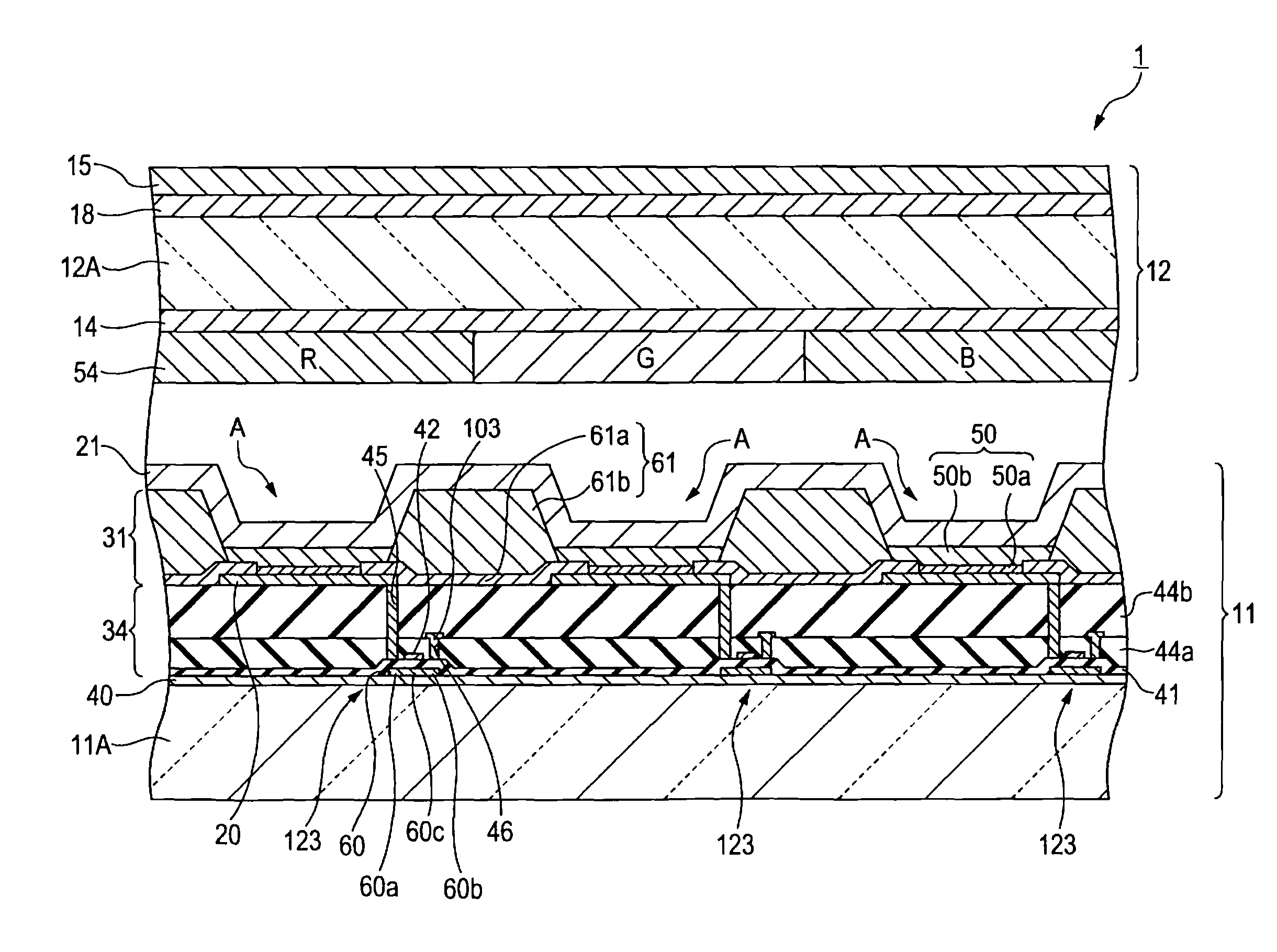
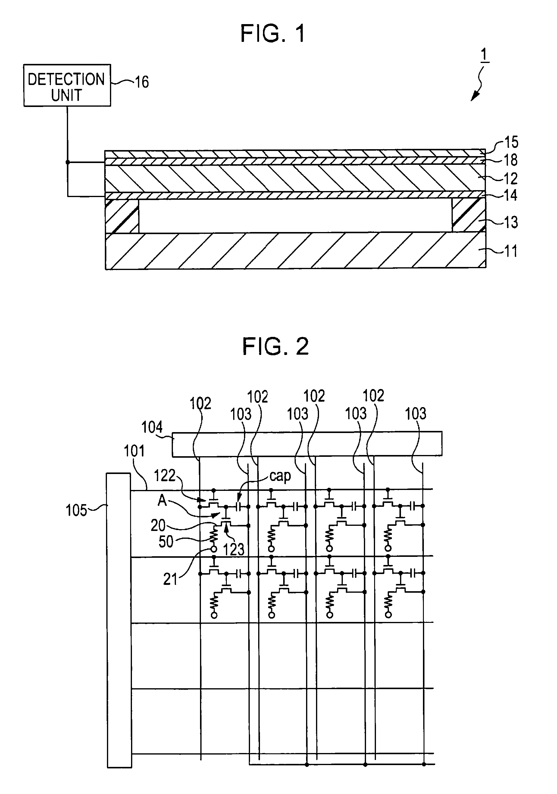
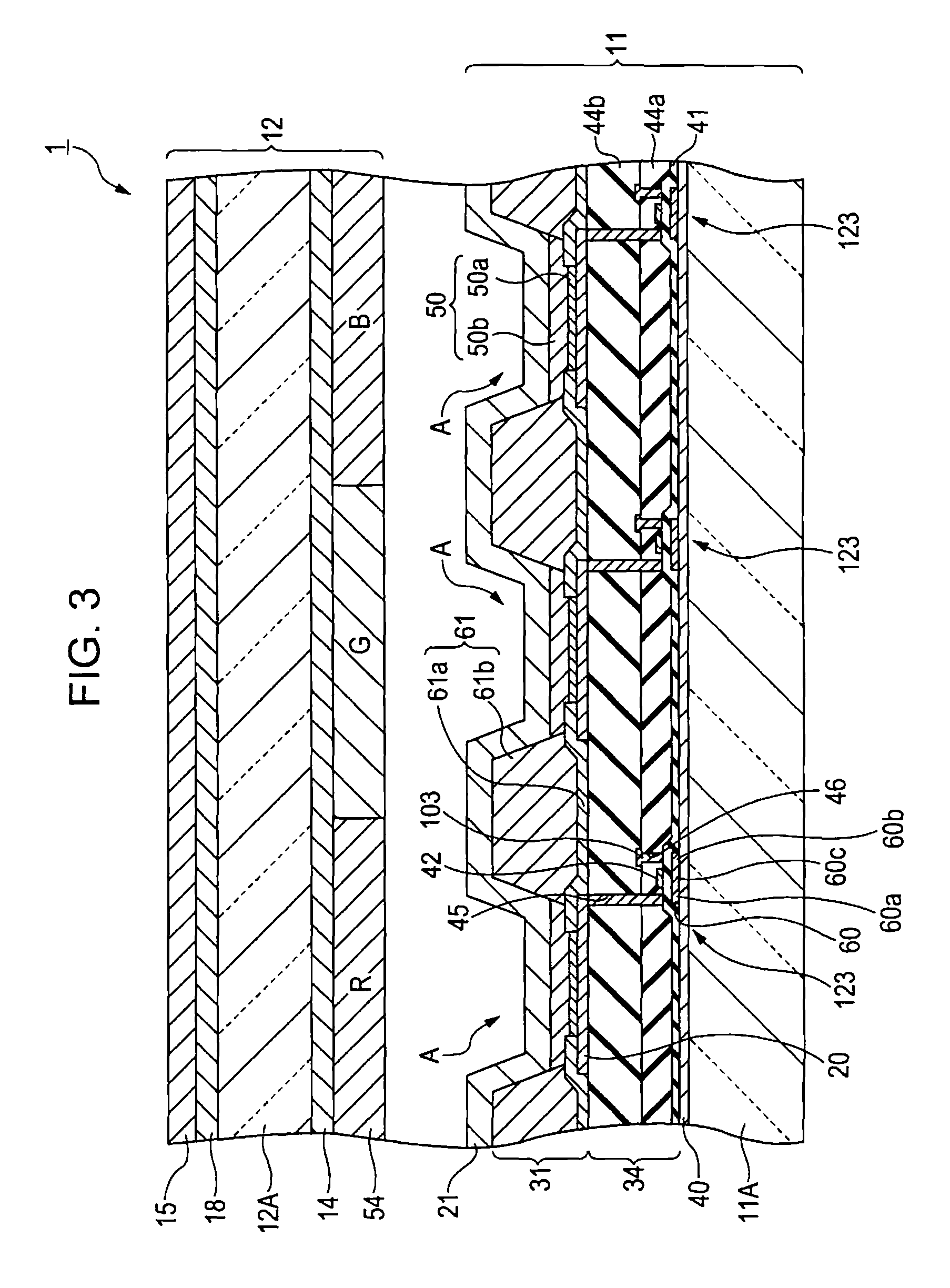
[0028]With reference to the accompanying drawings, an organic electroluminescence device having an input function according to a first exemplary embodiment of the present invention is described below. In the following description, for convenience of explanation, an “organic electroluminescence device having an input function” may be simply referred to as “organic EL device having an input function” or “touch-sensitive organic EL device”, where the term “touch-sensitive” is a non-limiting paraphrasing of “having an input function”, if the context allows. It should be noted that different scales are used for members illustrated in each of the accompanying drawings that are referred to in the following explanation so that each of the members illustrated therein has a size that is easily recognizable. FIG. 1 is a sectional view that schematically illustrates an example of the configuration of a touch-sensitive organic EL device (an organic electroluminescence device having an input func...

second embodiment

[0058]Next, with reference to the accompanying drawings, an organic EL device having an input function according to a second exemplary embodiment of the invention is explained below. FIG. 5 is a sectional view that schematically illustrates the layer configuration of sub pixel regions. An organic EL device having an input function according to the present embodiment of the invention differs from the organic EL device 1 having an input function according to the first exemplary embodiment of the invention described above only in terms of the configuration of a first detection electrode. That is, except for the first detection electrode, an organic EL device having an input function according to the present embodiment of the invention has the same configuration as that of the organic EL device 1 having an input function according to the first exemplary embodiment of the invention. Accordingly, in the following description, an explanation is given with a focus on the differentiating and...

third embodiment

[0066]Next, with reference to the accompanying drawings, an organic EL device having an input function according to a third exemplary embodiment of the invention is explained below. FIG. 7 is a sectional view that schematically illustrates the layer configuration of sub pixel regions. An organic EL device having an input function according to the present embodiment of the invention differs from the organic EL device 1 having an input function according to the first exemplary embodiment of the invention described above only in that, in the present embodiment of the invention, an individual light-emitting material corresponding to one of R, G, and B color components is provided in each of the sub pixel regions, thereby omitting a color filter layer. Except for the above difference, an organic EL device having an input function according to the present embodiment of the invention has the same configuration as that of the organic EL device 1 having an input function according to the fir...


PUM


Abstract

The invention provides an organic electroluminescence device having an input function, including: an element substrate that has a light-emitting layer sandwiched between a pair of electrodes; a sealing substrate that seals the element substrate; a first detection electrode that is provided at the inner-surface side of the sealing substrate; a second detection electrode that is provided at the outer-surface side of the sealing substrate; the second detection electrode having a detection axis that is not the same as that of the first detection electrode; a dielectric film that is formed on the second detection electrode; and a detection unit that detects a position at which electrostatic capacitance is generated via the dielectric film between the first detection electrode and the second detection electrode.

Description

BACKGROUND[0001]1. Technical Field[0002]The present invention relates to an organic electroluminescence device that has an input function. The invention further relates to an electronic apparatus that is provided with such an organic electroluminescence device.[0003]2. Related Art[0004]Small-sized information and electronic devices such as personal digital assistants (PDA) and personal computers have become widely used in recent years. With the increasing use of these devices, display devices having a so-called touch panel function have also come into wide use. A display device having a touch panel function allows a user to manually input instructions or the like therein; specifically, a user can make an input by contacting a touching object such as a finger, a pen, or the like, onto the display screen of such a touch-panel display device. In the technical field of touch panel display devices, a capacitive sensing scheme is known as an example of a method for detecting the contact p...

Claims


Application Information

Patent Timeline
Patent Type & Authority Patents(United States)
IPC IPC(8): H01J1/62H05B44/00
CPCG06F3/044H01L27/323H01L27/3244G06F3/0445G06F3/0446H10K59/40H10K59/12G06F3/03H05B33/02
Inventor KOSHIHARA, TAKESHIUTSUNOMIYA, SUMIOUSHIKI, TAKEYOSHIFUJIKAWA, YOICHI
Owner ELEMENT CAPITAL COMMERCIAL CO PTE LTD
Why Eureka
Try Eureka