Hydraulic drive system and method of operating a hydraulic drive system

a hydraulic drive and hydraulic drive technology, applied in the direction of fluid couplings, piston pumps, servomotors, etc., can solve the problems of difficult timing adjustment, affecting the speed of the piston, and adding to the cost of the system, so as to reduce the amount of energy wasted, prevent over-pressurization of the system, and increase the delay

Active Publication Date: 2010-06-22
WESTPORT FUEL SYST CANADA INC
View PDF15 Cites 30 Cited by
  • Summary
  • Abstract
  • Description
  • Claims
  • Application Information

AI Technical Summary

Benefits of technology

[0029]In a preferred embodiment the flow switching device is a four-way spool valve. The spool valve can be a two-position or three-position spool valve. With a four-way two-position spool valve the flow switching member comprises a spool member selectively movable to a first position wherein the first hydraulic fluid chamber is fluidly connected to receive hydraulic fluid from the hydraulic pump discharge outlet and the second hydraulic fluid chamber is fluidly connected to drain the hydraulic fluid through one of the low pressure conduits. When the spool member is in a second position the second hydraulic fluid chamber is fluidly connected to receive hydraulic fluid from the hydraulic pump discharge outlet and the first hydraulic fluid chamber is fluidly connected to drain the hydraulic fluid through one of the low pressure conduits. With a four-way three-position spool valve, a third position for the spool member is added wherein the hydraulic pump discharge outlet is in fluid communication with one of the low pressure conduits through which hydraulic fluid is returnable to the hydraulic fluid reservoir. In an open hydraulic system fluid in the hydraulic fluid reservoir is at atmospheric pressure, and the hydraulic fluid is returned from the flow switching valve to the reservoir. In a closed hydraulic system, the hydraulic fluid is returned from the flow switching valve to a low pressure conduit that delivers hydraulic fluid to the suction inlet of the hydraulic pump. Open hydraulic systems are simpler to operate and are more common.
[0032]The hydraulic pump can be mechanically driven by an internal combustion engine. For example, if the hydraulic drive system is employed to actuate machinery associated with the engine; such as a fuel pump, the hydraulic pump can be conveniently driven by the engine. To reduce pollution originating from engine emissions, engines using cleaner burning fuels such as natural gas and hydrogen are being developed. The presently disclosed hydraulic drive system could be employed to drive a cryogenic pump for pumping liquefied natural gas from a fuel tank to the engine's combustion chambers. In a preferred embodiment for a hydraulic drive system with an engine driven hydraulic pump, the controller can be configured to receive a signal from an engine speed sensor from which the controller can calculate that speed of the hydraulic pump.
[0034]The controller can be programmed to add a predetermined delay to the timing for sending the electronic signal to the flow switching device so that the piston is stationary for at least a predetermined time between each piston stroke. Factors such as component wear or transient speed conditions can cause variances between the calculated time when the piston reaches the end of a piston stroke and the actual time when this occurs. Accordingly, the controller can ensure that the piston completes its piston stroke before the hydraulic fluid flow is reversed by including a predetermined delay. However, energy is wasted while the piston is stopped and the hydraulic fluid flows through it, so it is preferable to keep the length of the delay short. An advantage of the disclosed hydraulic system is that the open shuttle valve stops piston movement independently from the reversal of hydraulic fluid flow so there is no danger of over-pressurizing the hydraulic cylinder and there is no need for a pressure relief valve.
[0051]In preferred embodiments, the shuttle valve is mechanically actuated to open when the piston is a predetermined distance from the cylinder head. The shuttle valve comprises a valve member that has a stem that extends towards the cylinder head, and when the piston is moving towards the cylinder head, contact between the stem and the cylinder head causes the valve member to be lifted away from a valve seat so that the valve member slides from a closed position to an open position. In the preferred method, the valve member is slidable from the open position back to the closed position by reversing the direction of hydraulic fluid flow and applying a differential pressure to the first and second hydraulic fluid chambers. The differential pressure acts on the shuttle valve member to move it towards a valve seat against which it is urged when in the closed position. An advantage of the preferred method and apparatus is that the shuttle valve can be very simple in construction, requiring only a valve member disposed in a valve cylinder, since it only requires differential fluid pressure and contact with the cylinder heads for actuation and shuttle valve actuation is independent from flow switching.
[0056]The method can further comprise incorporating a safety factor in the determination of when the hydraulic piston reaches the end position so that there is a delay between the time when it is determined that the piston has reached the end of the piston stroke and the time when the electronic signal is sent to the flow switching device. The safety factor can be changed depending upon the direction of hydraulic piston movement if hydraulic fluid pressure within the cylinder is dependent upon the direction of hydraulic piston movement, whereby the delay can be made longer if the hydraulic fluid pressure is higher. The method can further comprise monitoring hydraulic fluid pressure and changing the safety factor to increase the delay from a predetermined baseline if there is an increase in the hydraulic fluid pressure from a predetermined baseline pressure. As already noted, it is desirable to keep the delay short to reduce the amount of energy that is wasted, but an advantage of the present method is that the open shuttle valve prevents over-pressurization of the system and allows some leeway in setting the timing for reversing hydraulic fluid flow and this enables the present system to be simplified compared to conventional hydraulic systems.

Problems solved by technology

A disadvantage of such conventional arrangements is that it requires at least one position sensor that adds to the cost of the system.
With conventional arrangements such as this it can also be difficult to adjust the timing for reversing hydraulic fluid flow responsive to changes in hydraulic fluid flow rate, which affects piston velocity.
In addition, conventional systems like this often require a pressure relief valve to prevent over-pressurization of the hydraulic system, for example, if there is a malfunction of the position sensor.
However, fluid flow sensors are relatively expensive, and in a hydraulic system that employs a plurality of actuators, a fluid flow sensor is needed for each actuator.
However, a disadvantage of this solution is that it requires more mechanical components, which require more space, add more weight to the system, and add to manufacturing and maintenance costs.
A disadvantage of the valve disclosed by the '984 patent is the number of parts.

Method used


Image

  • Hydraulic drive system and method of operating a hydraulic drive system
  • Hydraulic drive system and method of operating a hydraulic drive system
  • Hydraulic drive system and method of operating a hydraulic drive system

Examples


Embodiment Construction

)

[0067]In the figures described herein, like reference numbers are employed to identify like features, and to be concise, if features described with respect to one figure are shown again and identified by the same reference number in another figure, the description of such features may not be repeated.

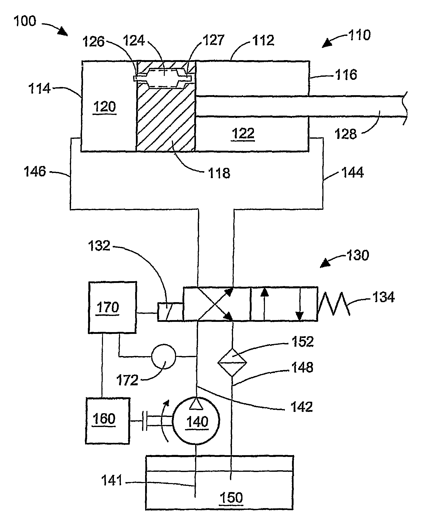
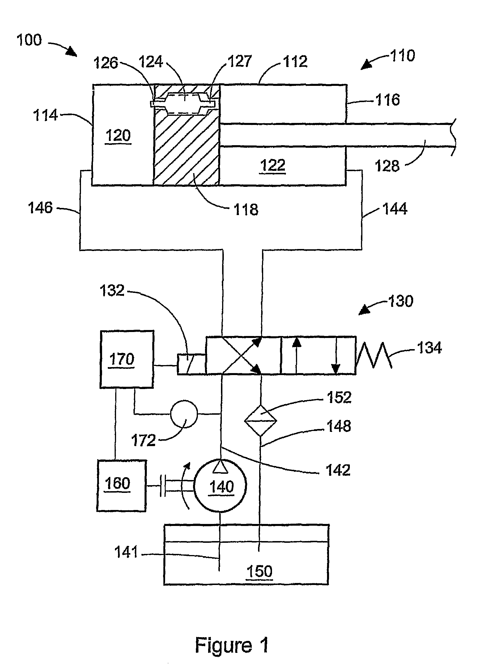
[0068]FIG. 1 is a schematic view of hydraulic drive system 100, which is operable to provide linear actuation to a machine (not shown). As noted above, there are many applications for hydraulic drive system 100, which has as its major components, hydraulic piston actuator 110, flow switching device 130, hydraulic pump 140, hydraulic fluid reservoir 150, motor 160, and electronic controller 170.

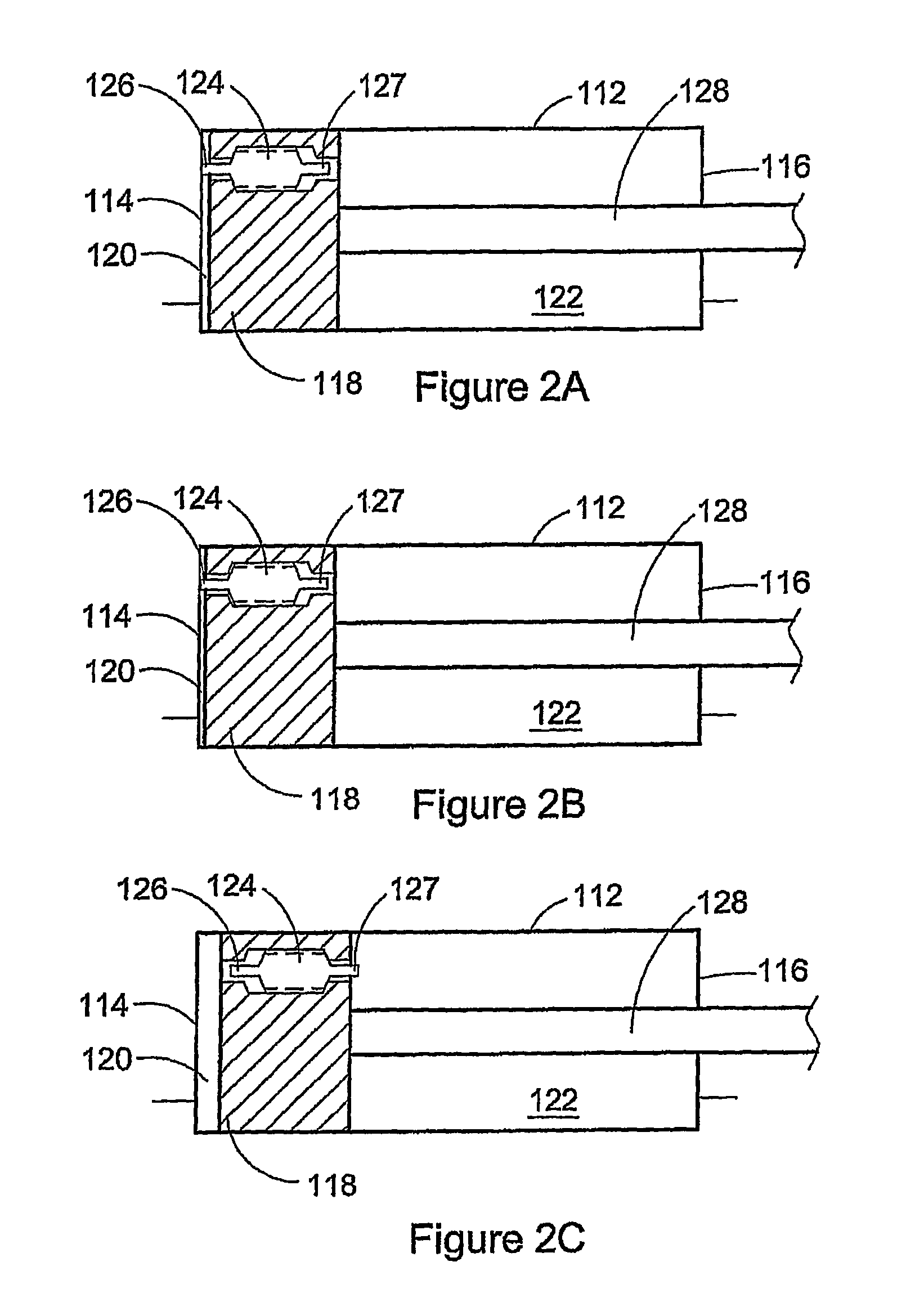
[0069]Hydraulic actuator 110 comprises hydraulic cylinder 112, which is sealed at each end by respective cylinder heads 114 and 116. Piston 118 is reciprocable within cylinder 112 and divides the interior of cylinder 112 into first hydraulic fluid chamber 120 and second hydraulic fluid chamber 12...


PUM


Abstract

A hydraulic drive system comprises a hydraulic actuator comprising a piston reciprocable between two cylinder heads for actuating a machine. A flow switching device reverses the direction of hydraulic fluid flow to and from chambers on opposite sides of the piston. The piston stops at the end of each piston stroke when a shuttle valve associated with the piston opens to allow hydraulic fluid to flow between the chambers cancelling the differential pressure that acts on the piston to cause reciprocal movement. A controller is programmed to determine when the piston reaches the end of each stroke based upon at least one of hydraulic pump speed, hydraulic fluid pressure, or elapsed time, with each of these measured during each stroke. The controller then sends an electronic signal to command the flow switching device to reverse the direction of hydraulic fluid flow.

Description

CROSS-REFERENCE TO RELATED APPLICATION(S)[0001]This application is a continuation of International Application No. PCT / CA2005 / 001218, having an international filing date of Aug. 5, 2005, entitled “Hydraulic Drive System And Method Of Operating A Hydraulic Drive System”. International Application No. PCT / CA2005 / 001218 claimed priority benefits, in turn, from Canadian Patent Application No. 2,476,032 filed Aug. 27, 2004. International Application No. PCT / CA2005 / 001218 is hereby incorporated by reference herein in its entirety.FIELD OF THE INVENTION[0002]The present invention relates to a hydraulic drive system and a method of operating a hydraulic drive system. More particularly, the invention relates to a system and method that employs a reciprocating hydraulically actuated piston connectable to a machine by a piston rod.BACKGROUND OF THE INVENTION[0003]Hydraulic drive systems that employ a reciprocating piston can be employed to provide reciprocating actuation for a wide variety of ...

Claims


Application Information

Patent Timeline
Patent Type & Authority Patents(United States)
IPC IPC(8): F15B15/28F15B15/00F15B11/15F15B15/20
CPCF15B11/15F15B15/2838F15B15/204
Inventor NOBLE, STEPHENHARPER, GREGBROOK, THOMAS
Owner WESTPORT FUEL SYST CANADA INC
Why Eureka
Try Eureka