
Apparatus for analysing surface properties with indirect illumination

a technology of surface properties and apparatus, applied in the field of apparatus and a method for determining surface properties, to achieve the effect of better matching

Active Publication Date: 2010-06-22
BYK GARDNER
View PDF6 Cites 8 Cited by
  • Summary
  • Abstract
  • Description
  • Claims
  • Application Information

AI Technical Summary

Benefits of technology

[0010]In one preferred embodiment, the radiation scattering device is essentially completely surrounded by a radiation-absorbent region. This prevents the radiation scattering device from being inadvertently hit also by rays from the radiation device, and in this way prevents any mixing between the indirect and the direct illumination of the surface. The radiation scattering device according to the invention is also intended in particular to bring about the situation whereby the indirect illumination and the direct irradiation of the surface are completely separate from one another and for example the direct irradiation does not also have indirect components.
[0014]In a further advantageous embodiment, two radiation scattering devices are provided which are arranged symmetrically with respect to the centre plane, and also two illumination devices which respectively illuminate the radiation scattering devices located opposite them with respect to the centre plane. In this way, it is possible to simulate in a particularly efficient manner diffuse radiation coming from all sides.
[0016]In one preferred embodiment, the or at least one radiation detector device allows local resolution of the radiation impinging thereon. In this way, a locally resolved image can be output. In this case, the radiation detector device may in particular have a CCD chip or the like which outputs a locally resolved image of the radiation impinging thereon.
[0022]In a further preferred embodiment, a third radiation scattering device or a radiation scattering body is provided which runs at least in some sections in the centre plane. Preferably, this is a region which is thus arranged at least partially above the surface to be analysed and preferably is arranged essentially vertically above the latter. This region may also be partially illuminated by the illumination device, and in this way an even better match to natural scattered light can be achieved.

Problems solved by technology

However, since the human eye is suitable only to a limited extent for the objective determination of surface properties, there is a need for aids and apparatuses for the qualitative and quantitative determination of surface properties.

Method used


Image

  • Apparatus for analysing surface properties with indirect illumination
  • Apparatus for analysing surface properties with indirect illumination
  • Apparatus for analysing surface properties with indirect illumination

Examples


Embodiment Construction

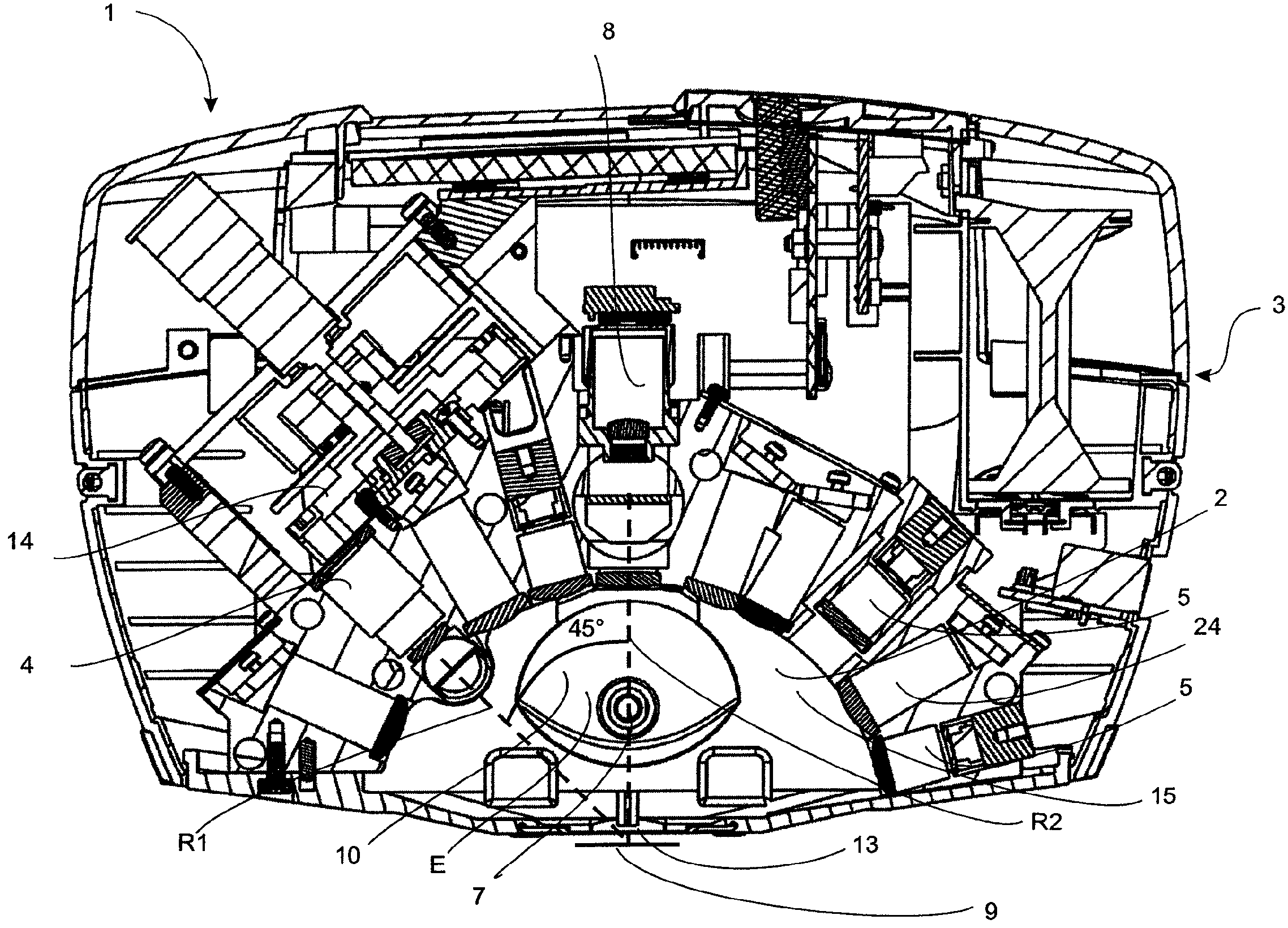
[0034]FIG. 1 shows a side view of an apparatus 1 according to the invention for analysing surface properties. This apparatus comprises a first radiation device 4 which emits radiation along the direction R1 onto a surface 9 to be analysed. For this purpose, the housing 3 of the apparatus has an opening 13, through which the radiation can pass and impinge on the surface 9. This opening 13 is essentially the only opening of the housing. In this way, it is possible to prevent disruptive external light from passing into the observation area 2 of the apparatus. Reference 8 denotes a radiation detector device which serves to receive the light that is thrown back from the surface 9, i.e. in particular the light that is reflected and / or scattered by the surface 9. The first radiation device 4 is arranged here at an angle of 45° with respect to the centre vertical line R2. Reference R2 denotes the direction which extends between the surface 9 and the radiation detector device 8. Together, th...


PUM

PropertyMeasurementUnit
wavelength rangeaaaaaaaaaa
angleaaaaaaaaaa
surface propertiesaaaaaaaaaa

Abstract

An apparatus (1) for analysing surface properties, comprising a first radiation device (4) which emits radiation directly onto a surface (9) to be analyzed, a first illumination device (6, 7) for indirectly illuminating the surface (9) to be analyzed, a first radiation detector device (8) which receives at least part of the radiation thrown back from the surface (9) to be analyzed and outputs at least one signal which is characteristic of this part of the radiation. According to the invention, a radiation scattering device (10, 11) is provided which is at least partially illuminated by the first illumination device (6, 7) and which transmits scattered radiation onto the surface (9) to be analyzed.

Description

FIELD OF THE INVENTION[0001]The present invention relates to an apparatus and a method for determining surface properties. The invention will be described with reference to surfaces of motor vehicles. However, it is pointed out that the invention can also be used on other surfaces, for example the coatings of furniture, of floor coverings and the like.BACKGROUND OF THE INVENTION[0002]The optical impression of objects or of the surfaces thereof, particularly surfaces on motor vehicles, is greatly determined by the surface properties thereof. However, since the human eye is suitable only to a limited extent for the objective determination of surface properties, there is a need for aids and apparatuses for the qualitative and quantitative determination of surface properties.[0003]Surface properties such as, for example, gloss, orange peel, colour, macrostructure or microstructure, image sharpness, haze, surface structure and / or surface topography and the like are determined.[0004]The p...

Claims


Application Information

Patent Timeline
Patent Type & Authority Patents(United States)
IPC IPC(8): G01N21/86G01N21/00G01N21/47
CPCG01N21/55G01N21/474G01N21/4738G01N2021/4754
Inventor SCHWARZ, PETERSPERLING, UWE
Owner BYK GARDNER
Learn More