Measuring apparatus

a technology of measuring apparatus and measuring head, which is applied in the direction of distance measurement, instruments, surveying and navigation, etc., can solve the problems of no longer meeting the operating requirements, no longer offering adequate protection, and drastically worsening the cooling of the turbine blade, so as to facilitate the calibration of the measuring head, reduce the measurement time and positioning errors, and improve the effect of accuracy

Inactive Publication Date: 2010-06-29
ANSALDO ENERGIA IP UK LTD
View PDF8 Cites 28 Cited by
  • Summary
  • Abstract
  • Description
  • Claims
  • Application Information

AI Technical Summary

Benefits of technology

[0008]One of numerous aspects of the present invention relates to a measuring apparatus with the aid of which it is possible, in particular, for cooling air bores in turbine blades to be detected and recorded in a particularly reliable fashion, and thereby reliable cooling of the turbine blades after renewal of a thermal barrier coating can thereby being ensured.
[0009]Another aspect of the present invention is based on the general idea of providing, on a measuring apparatus, a measuring head that holds a distance measuring device, a camera apparatus, and an illumination device, and that is designed for the contactless detection of a distance between a surface of the measurement object and the measuring apparatus, and at the same time detects the surface of the measurement object visually, likewise in a contactless fashion. Particular attention is accorded here to a compact design, as large an operating distance as possible from the measurement object, a resolution / magnification optimized for the application, and a high-intensity, preferably coaxial illumination. In this case, the operating point on the surface of the measurement object is illuminated by the illumination device in a fashion as free as possible from shadows and simultaneously recorded by the camera apparatus or is focused and measured by the distance measuring device. In order to be able to achieve the most compact design possible, there is located, on an optical axis between the illumination device and an operating point on the surface of the measurement object, a mirror and filter device that has at least one dichroic mirror that transmits or reflects light beams as a function of their wavelength and thereby splits light reflected by the operating point between the distance measuring device and the camera apparatus. The common operating point facilitates the calibration of the measuring head on a measuring machine such as, for example, a robot. By comparison with individual operating points, machine movements, and therefore measuring time and positioning errors, can be reduced with the aid of the inventive measuring apparatus that operates with a single operating point for imaging and distance measurement.
[0010]The inventive mirror and filter device, which uses the dichroic mirror to split the reflected light beams between the distance measuring device and the camera apparatus as a function of their wavelength, renders it possible to record both the distance from the surface and a visual image thereof, this being done, moreover, with the aid of a very compact measuring head that is particularly suitable for operating at sites with difficult access, owing to its small overall space requirement.

Problems solved by technology

However, after these intervals it is chiefly the anti-oxidations layers that are consumed, and they no longer offer adequate protection, and so the turbine blade has to be removed and replaced.
However, during the coating of used turbine blades the problem occurs that the originally open cooling air bores are stopped by the renewed coating with the metallic anti-oxidation layer or with the ceramic thermal barrier coating, the result being that the cooling of the turbine blades is drastically worsened and no longer satisfies the operating requirements.
For example, the red spectrum is likewise contained in white light, and this can have a disadvantageous effect on the signal quality of the distance measuring device.

Method used


Image

  • Measuring apparatus
  • Measuring apparatus
  • Measuring apparatus

Examples


Embodiment Construction

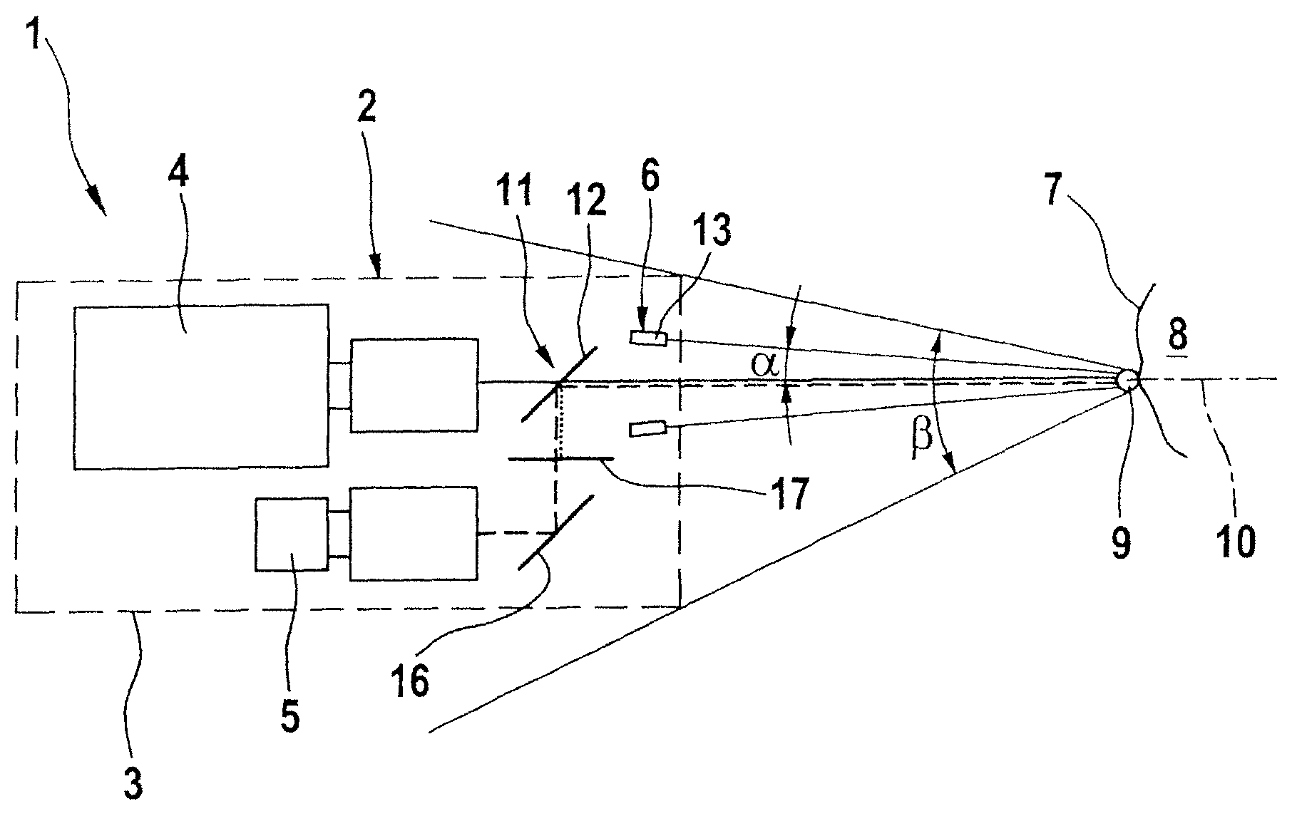
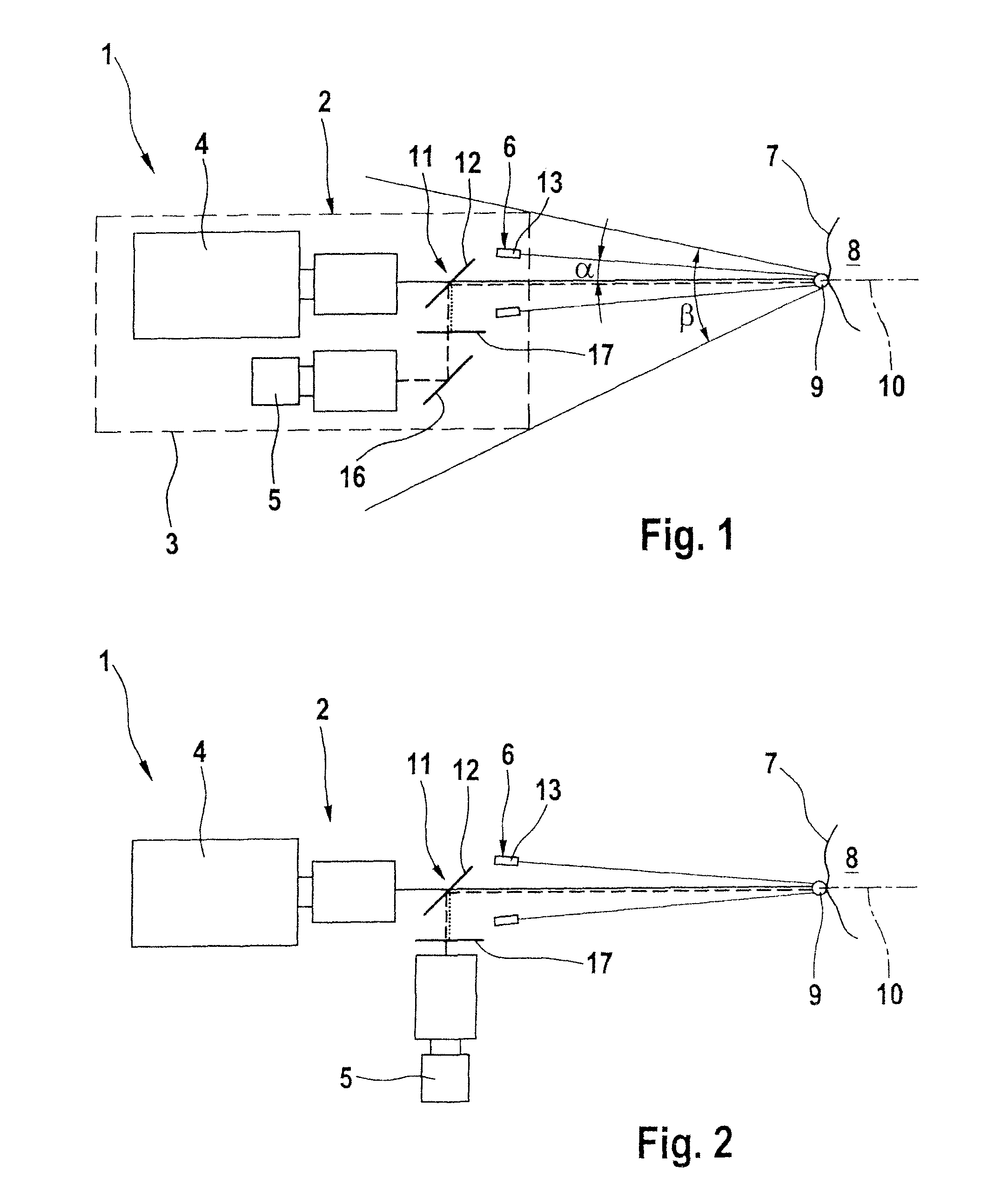
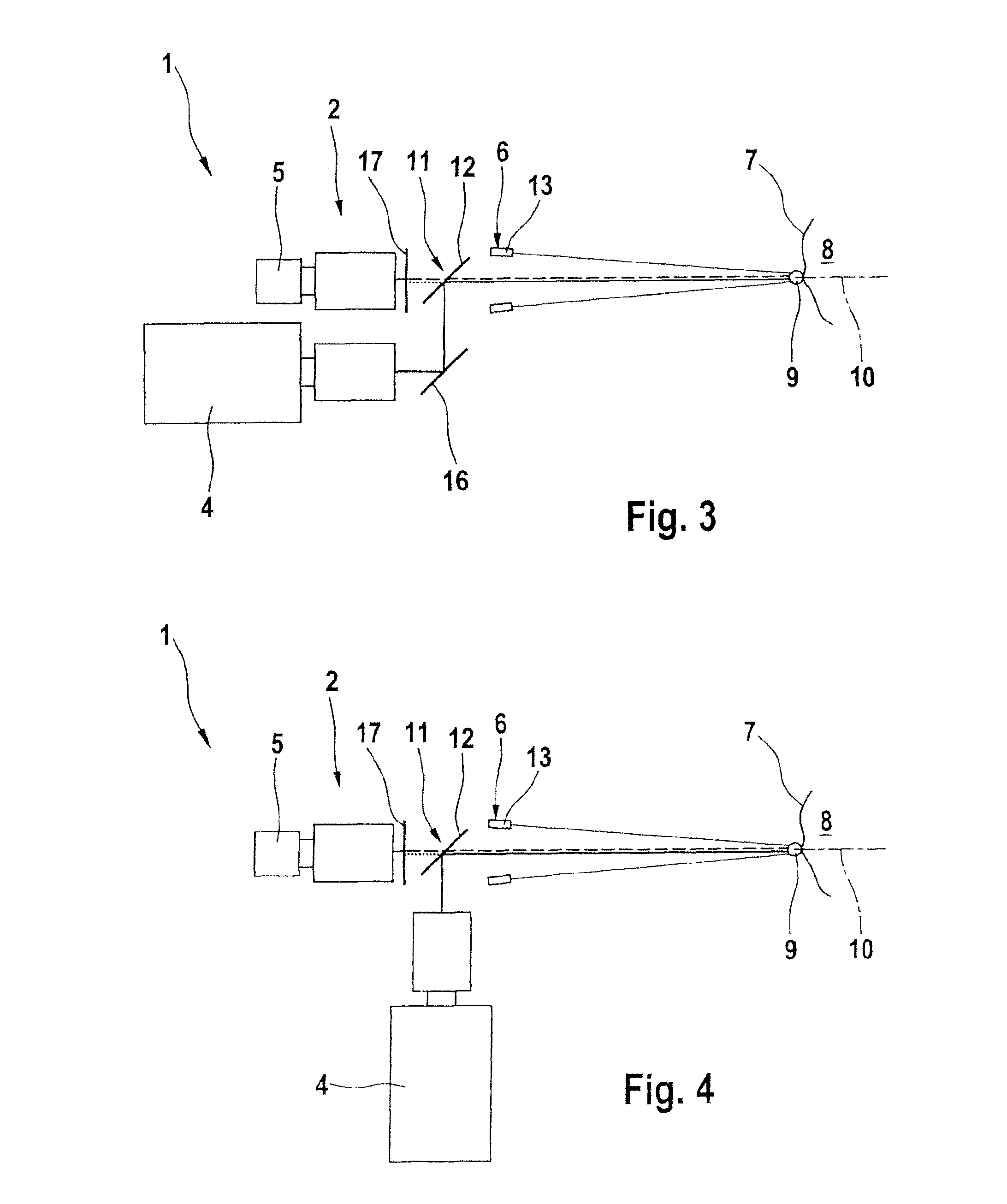
[0027]According to FIG. 1, a measuring apparatus 1 has a measuring head 2 that is arranged in a housing 3, and a distance measuring device 4, a camera apparatus 5 and an illumination device 6. The measuring apparatus 1 is designed for the contactless detection of a distance between a surface 7 of a measurement object 8 and the measuring apparatus 1, as well as simultaneously detecting the surface 7 in a contactless, visual fashion. Here, the illumination device 6 illuminates an operating point 9 on the surface 7 of the measurement object 8, which is simultaneously focused on by the camera apparatus 5 and the distance measuring device 4. According to this exemplary embodiment, there is also provided, on an optical axis 10, a mirror and filter device 11 that has at least one dichroic mirror 12 that transmits or reflects light beams as a function of their wavelength and thereby splits light reflected by the operating point 9 between the distance measuring device 4 and the camera appara...


PUM


Abstract

A measuring apparatus (1) for contactless detection of a distance between a surface (7) of a measurement object (8) and the measuring apparatus (1), and for simultaneous contactless visual detection of the surface (7), has a measuring head (2) holding a distance measuring device (4), a camera apparatus (5) and an illumination device (6), the illumination device (6) illuminating an operating point (9) on the surface (7) of the measurement object (8) that is simultaneously focused by the camera apparatus (5) and the distance measuring device (4). On an optical axis (10), between the illumination device (6) and the operating point (9), a mirror and filter device (11), that has at least one dichroic mirror (12) that transmits or reflects light beams as a function of wavelength, and thereby splits light reflected by the operating point (9) between the distance measuring device (4) and the camera apparatus (5), is provided.

Description

[0001]This application is a Continuation of, and claims priority under 35 U.S.C. §120 to, International application no. PCT / EP2006 / 069642, filed 13 Dec. 2006, and claims priority therethrough under 35 U.S.C. §§119, 365 to Swiss application no. 00169 / 06, filed 2 Feb. 2006, the entireties of which are incorporated by reference herein.BACKGROUND[0002]1. Field of Endeavor[0003]The present invention relates to a measuring apparatus for contactless detection of a distance between a surface of a measurement object and the measuring apparatus, and for simultaneous contactless visual detection of the surface.[0004]2. Brief Description of the Related Art[0005]During the operation of a gas turbine, the most strongly loaded gas turbine blades of the first stage are exposed to hot gas temperatures of above 1400° C. For their protection, these are therefore provided with metallic anti-oxidation layers and, frequently, additionally with ceramic thermal barrier coatings (TBCs). A reliable operation...

Claims


Application Information

Patent Timeline
Patent Type & Authority Patents(United States)
IPC IPC(8): G01C3/08
CPCG01B11/14G01B11/026
Inventor FRANITZA, KARSTENFEHRMANN, BERNDHOEBEL, MATTHIASLANG, PETER
Owner ANSALDO ENERGIA IP UK LTD
Why Eureka
Try Eureka