
Flow shifting coolant during freeze start-up to promote stack durability and fast start-up

a technology of coolant and freeze start-up, which is applied in the field of fuel cells, can solve the problems of large temperature variation in the down-the-channel temperature of the cell, the cost of catalysts is typically costly precious metal particles, and the cost of membrane electrode assemblies is relatively high to manufactur

Inactive Publication Date: 2010-07-06
GM GLOBAL TECH OPERATIONS LLC
View PDF30 Cites 10 Cited by
  • Summary
  • Abstract
  • Description
  • Claims
  • Application Information

AI Technical Summary

Benefits of technology

The auxiliary coolant system achieves a more even temperature distribution across the fuel cell stack, enhancing MEA durability and enabling faster start-ups while reducing mechanical stress and operational costs.

Problems solved by technology

The catalytic particles are typically costly precious metal particles.
These membrane electrode assemblies are relatively expensive to manufacture and require certain conditions, including proper water management and humidification, and control of catalyst fouling constituents such as carbon monoxide (CO), for effective operation.
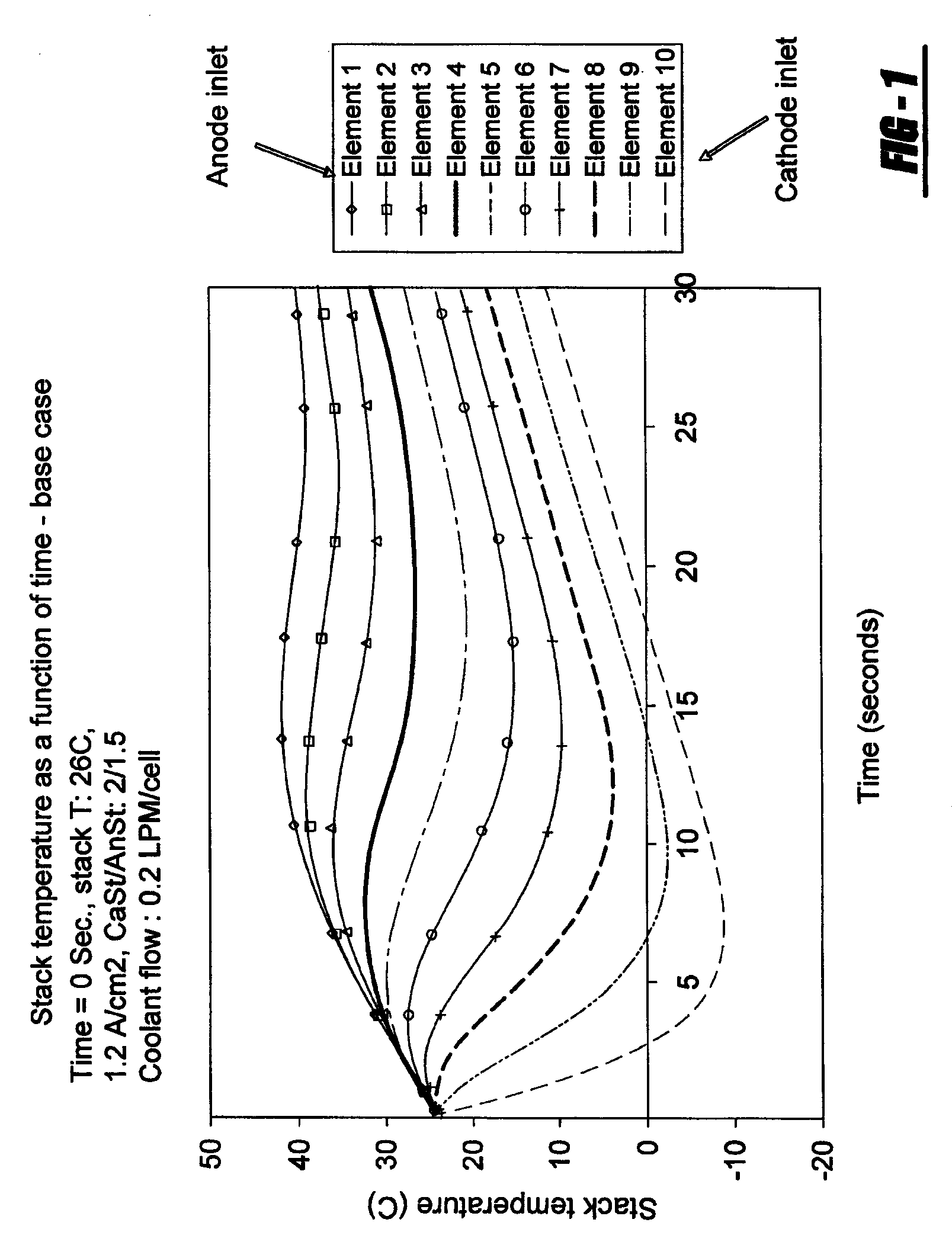
Such an operating strategy can cause a large down-the-channel temperature variation within a cell, because the cold coolant stream will quench the section of the plate near the coolant inlet, while the amount of coolant does not have enough cooling capacity to control the temperature of the plate near the coolant outlet.
Such a wide temperature distribution within a cell can result in poor distribution of RH, in that the membrane at the high temperature zone is relatively dry while the membrane at the low temperature zone is very wet, thus reducing the MEA durability.
In addition, such a wide temperature distribution could have negative impact on the mechanical stress of the bipolar plate, MEA, DM and / or the like.
However, the mechanization utilizing the in-line heater will cost more, and will consume power, thus resulting in lower fuel efficiency.

Method used


Image

  • Flow shifting coolant during freeze start-up to promote stack durability and fast start-up
  • Flow shifting coolant during freeze start-up to promote stack durability and fast start-up
  • Flow shifting coolant during freeze start-up to promote stack durability and fast start-up

Examples


Embodiment Construction

[0024]The following description of the preferred embodiment(s) is merely exemplary in nature and is in no way intended to limit the invention, its application, or uses.

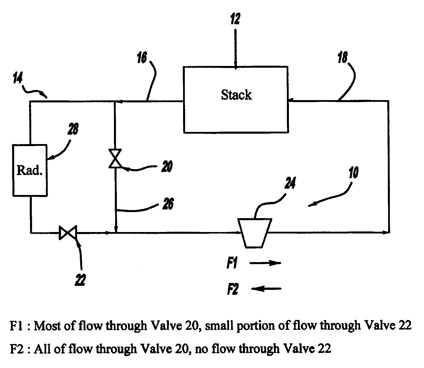
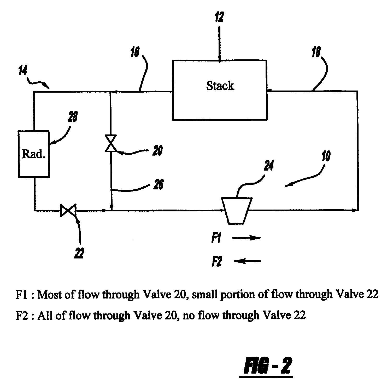
[0025]In order to avoid the large temperature distribution within a cell during freeze start-up and enable fast start-up of fuel cell system, a coolant flow shifting operation system and methodology is proposed in accordance with the general teachings of the present invention.

[0026]Referring to FIG. 2, there is shown a schematic view of an auxiliary coolant system 10 for a fuel cell stack system 12, in accordance with the general teachings of the present invention. A primary coolant system 14 is shown in fluid communication with both the auxiliary coolant system 10 and the fuel cell stack system 12. Various conduits, pipes and / or the like can be employed to provide fluid communication among the three systems, as is known in the art.

[0027]In this operating methodology, during start-up, subzero coolant is introduced to ...


PUM

PropertyMeasurementUnit
temperatureaaaaaaaaaa
stack operating temperatureaaaaaaaaaa
volumeaaaaaaaaaa

Abstract

An auxiliary coolant system, for a fuel cell stack system, includes a reversible coolant pump, a control valve, and plumbing lines. The pump enables the reversal of the coolant flow direction in the fuel cell stack system. The auxiliary coolant system is in parallel with the primary coolant system, and communicates with the primary coolant system via valves. During start-up, when coolant flow is from right-to-left through the fuel cell stack system, one valve of the primary coolant system will be partly open and control the amount of cold coolant make-up from the primary coolant system to the fuel cell stack while the valve of the auxiliary coolant system will be controlling the temperature differential between the inlet and outlet of the stack.

Description

FIELD OF THE INVENTION[0001]The present invention relates generally to fuel cells, and more particularly to coolant systems for fuel cell stack systems.BACKGROUND OF THE INVENTION[0002]Fuel cells have been used as a power source in many applications. For example, fuel cells have been proposed for use in electrical vehicular power plants to replace internal combustion engines. In PEM-type fuel cells, hydrogen is supplied to the anode of the fuel cell and oxygen is supplied as the oxidant to the cathode. PEM fuel cells include a membrane electrode assembly (MEA) comprising a thin, proton transmissive, non-electrically conductive solid polymer electrolyte membrane having the anode catalyst on one of its faces and the cathode catalyst on the opposite face. The MEA is sandwiched between a pair of electrically conductive elements, sometimes referred to as the gas diffusion media (DM) components, that: (1) serve as current collectors for the anode and cathode; (2) contain appropriate openi...

Claims


Application Information

Patent Timeline
Patent Type & Authority Patents(United States)
IPC IPC(8): H01M2/00H01M8/00
CPCH01M8/04029Y10T29/49002Y02E60/50H01M8/04223H01M8/241H01M8/04225H01M8/0267H01M8/2483
Inventor ZHANG, YANFAGLEY, JOHN C.
Owner GM GLOBAL TECH OPERATIONS LLC
Learn More