Microlens and an image sensor including a microlens

a microlens and image sensor technology, applied in the field of microlens and image sensor including a microlens, can solve the problems of image sensor malfunction, difficult to decrease the area between the photoresist pattern prp less than a predetermined value, and degrade optical efficiency, so as to increase optical efficiency and optical efficiency

Inactive Publication Date: 2010-07-06
SAMSUNG ELECTRONICS CO LTD
View PDF52 Cites 4 Cited by
  • Summary
  • Abstract
  • Description
  • Claims
  • Application Information

AI Technical Summary

Benefits of technology

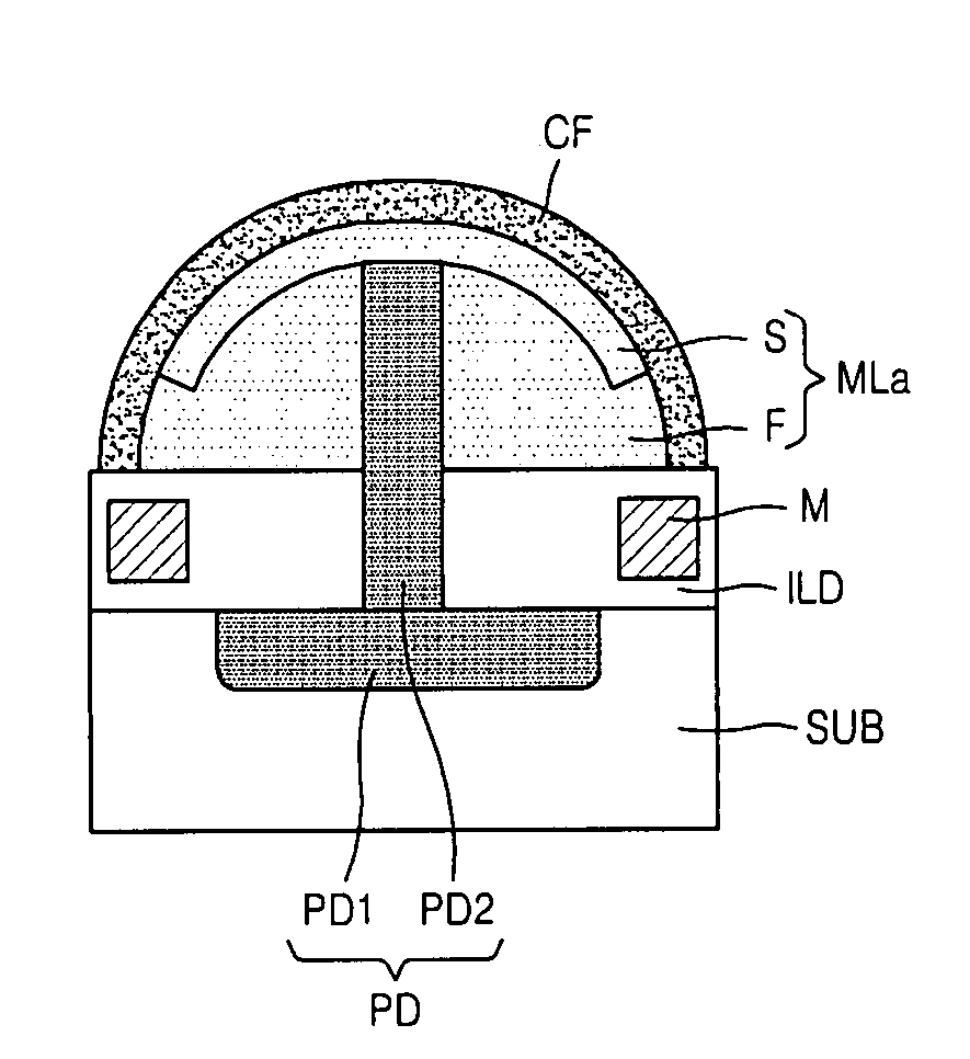
[0022]Example embodiments provide a method of forming a microlens which decreases the optical efficiency degradation caused by the formation of a dead zone in an image sensor and simultaneously increases the light concentration. Example embodiments provide a microlens including a polysilicon pattern formed on a semiconductor substrate, a round-type shell portion for the microlens, wherein the round-type shell portion encloses the polysilicon pattern, and a filler material filling an interior of the shell portion. The polysilicon pattern may have a cylindrical shape.

Problems solved by technology

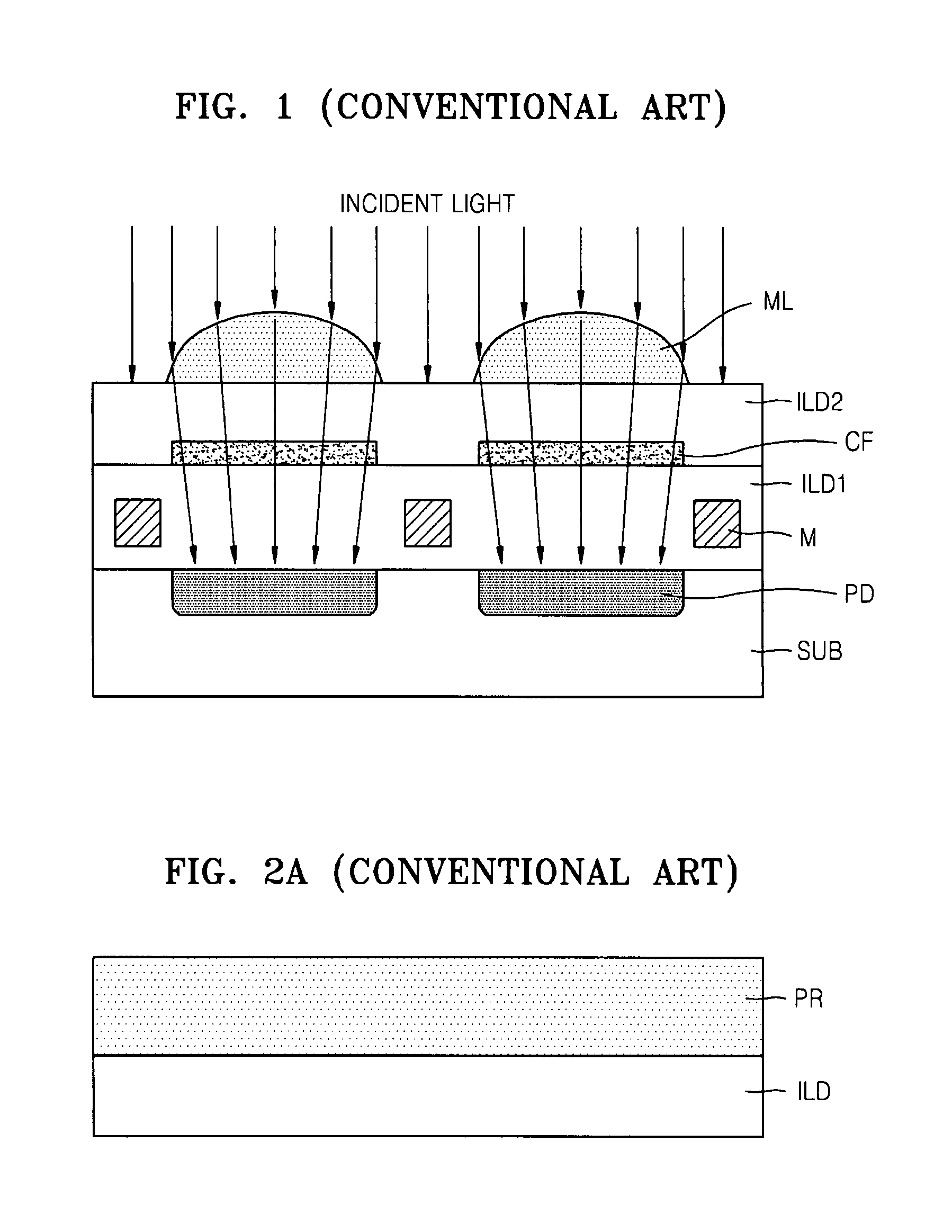
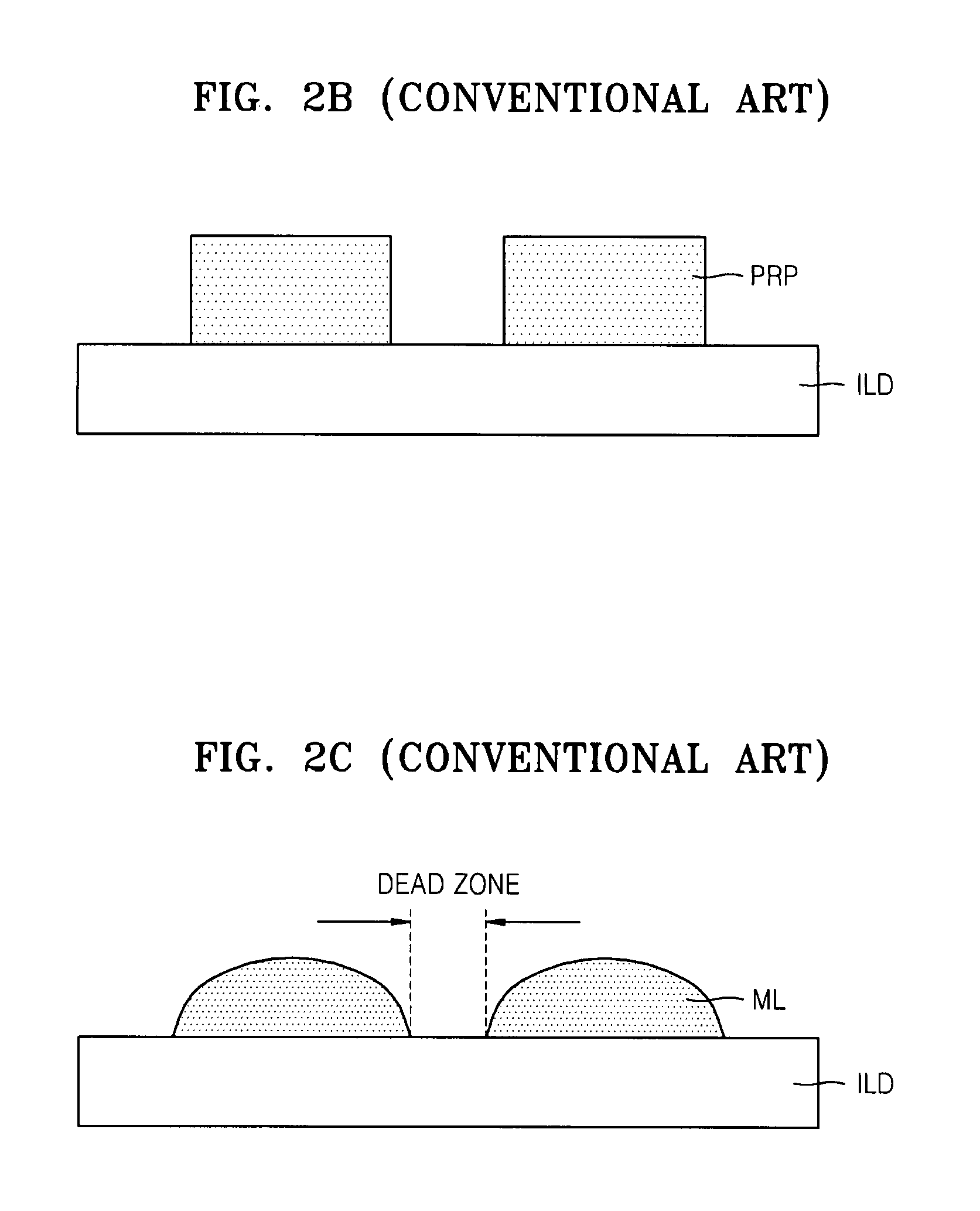
In the conventional image sensor, the optical efficiency is degraded because a dead zone (an area where light cannot be concentrated) exists between the microlenses.
Due to the limits in resolution of exposure equipment, it is difficult to decrease the area between the photoresist pattern PRP less than a predetermined value.
If the incident light is input inclined, then a portion of the incident light passing through the microlens ML may not reach the photodiode PD corresponding thereto, causing the image sensor to malfunction.

Method used


Image

  • Microlens and an image sensor including a microlens
  • Microlens and an image sensor including a microlens
  • Microlens and an image sensor including a microlens

Examples


Embodiment Construction

[0067]Various example embodiments will now be described more fully with reference to the accompanying drawings in which some example embodiments are shown. In the drawings, the thicknesses of layers and regions may be exaggerated for clarity.

[0068]Detailed illustrative embodiments are disclosed herein. However, specific structural and functional details disclosed herein are merely representative for purposes of describing example embodiments. This invention may, however, may be embodied in many alternate forms and should not be construed as limited to only the example embodiments set forth herein.

[0069]Accordingly, while the example embodiments are capable of various modifications and alternative forms, embodiments thereof are shown by way of example in the drawings and will herein be described in detail. It should be understood, however, that there is no intent to limit example embodiments to the particular forms disclosed, but on the contrary, the example embodiments are to cover ...


PUM

PropertyMeasurementUnit
glass transition temperature Tgaaaaaaaaaa
heightaaaaaaaaaa
dielectricaaaaaaaaaa

Abstract

A microlens, an image sensor including the microlens, a method of forming the microlens and a method of manufacturing the image sensor are provided. The microlens includes a polysilicon pattern, having a cylindrical shape, formed on a substrate, and a round-type shell portion enclosing the polysilicon pattern. The microlens may further include a filler material filling an interior of the shell portion, or a second shell portion covering the first shell portion. The method of forming a microlens includes forming a silicon pattern on a semiconductor substrate having a lower structure, forming a capping film on the semiconductor substrate over the silicon pattern, annealing the silicon pattern and the capping film altering the silicon pattern to a polysilicon pattern having a cylindrical shape and the capping film to a shell portion for a round-type microlens, and filling an interior of the shell portion with a lens material through an opening between the semiconductor substrate and an edge of the shell portion. The image sensor includes a microlens formed by a similar method and a photodiode having a cylindrical shape.

Description

PRIORITY STATEMENT[0001]This U.S. non-provisional application claims the benefit of priority under 35 U.S.C. §119 from Korean Patent Application No. 10-2006-0070296, filed on Jul. 26, 2006, in the Korean Intellectual Property Office (KIPO), the disclosure of which is incorporated herein in its entirety by reference.BACKGROUND[0002]1. Field[0003]Example embodiments relate to an image sensor including a microlens, an image sensor including the microlens, a method of forming the microlens and a method of manufacturing the image sensor. Other example embodiments relate to a method of forming a microlens which increases an optical efficiency, a microlens capable of increasing optical efficiency, an image sensor including the microlens and a method of manufacturing the image sensor.[0004]2. Description of the Related Art[0005]Microlenses are used in a variety of fields (e.g., image sensors, liquid crystal display (LCD) devices and optical communications systems). Microlenses can be used a...

Claims


Application Information

Patent Timeline
Patent Type & Authority Patents(United States)
IPC IPC(8): H01L31/062H01L31/107G02B3/00H01L27/14H01L27/146H04N5/335H04N5/369H04N5/372H04N5/374
CPCH01L27/14627H01L27/14685H01L31/0232H01L27/14621H01L27/14632H01L27/14687H01L31/02327H01L27/14
Inventor YIN, HUAXIANGLIM, HYUCKPARK, YOUNG-SOOXIANYU, WENXUCHO, HANS S.
Owner SAMSUNG ELECTRONICS CO LTD
Why Eureka
Try Eureka