Frequency measurement based frequency locked loop synthesizer

a frequency lock and loop technology, applied in pulse manipulation, pulse technique, instruments, etc., can solve the problem of providing a less than desirable settling time, and achieve the effect of reducing tuning times, reducing gain and resolution of fll control loops, and fast settling tim

Active Publication Date: 2010-07-06
QORVO US INC
View PDF4 Cites 42 Cited by
  • Summary
  • Abstract
  • Description
  • Claims
  • Application Information

AI Technical Summary

Benefits of technology

[0005]A first embodiment of the present invention relates to a frequency and phase locked loop (FPLL) synthesizer having a frequency-locked loop (FLL) with an FLL operating mode and a phase-locked loop (PLL) with a PLL operating mode. The FLL operating mode is used for rapid coarse tuning of the FPLL synthesizer and is followed by the PLL operating mode for fine tuning and stabilization of the frequency of an output signal from the FPLL synthesizer. The FPLL synthesizer includes a variable frequency oscillator having a coarse tuning control input and a fine tuning control input. The coarse tuning control input is controlled by FLL circuitry, and the fine tuning input is controlled by PLL circuitry. The use of a frequency-locked loop allows faster settling time for the coarse tuning value than prior art linear and binary search methods. The FLL operating mode may be sub-divided into an FLL acquisition mode for rapid frequency tuning, and an FLL average and interpolate mode to complete frequency tuning before switching to the PLL operating mode.
[0006]In a second embodiment of the present invention, the FPLL synthesizer may include frequency reduction circuitry for reducing the frequency of the output signal for use in the FLL and PLL circuitry. The FLL circuitry may include frequency detection circuitry for measuring the frequency error of the frequency reduced output signal, and a loop filter to control the bandwidth of an FLL control loop formed by the FLL circuitry and the variable frequency oscillator. The PLL circuitry may include phase detection circuitry for measuring the phase error of the frequency reduced output signal and a loop filter to control the bandwidth of a PLL control loop formed by the PLL circuitry and the variable frequency oscillator. Since the frequency reduction circuitry within the FLL circuitry reduces the frequency of the output signal, the gain and resolution of the FLL control loop may also be reduced, as in the case of using a frequency divider; therefore, the FLL control loop may include gain elements, such as analog gain elements, digital gain elements, or both, to recover some of the gain. To reduce tuning times, the gain of the FLL control loop may be higher during the FLL acquisition mode than during the FLL average and interpolate mode.
[0007]In one embodiment of the present invention, the FPLL synthesizer is a translational loop FPLL synthesizer, which may also be called an offset or dual loop FPLL that may use a local oscillator (LO) FPLL synthesizer to provide a reference signal to a primary FLL, primary PLL, or both. The LO FPLL synthesizer may have a coarse tuning mode and a fine tuning mode, and the primary FLL may begin coarse tuning before the LO FPLL synthesizer is completely settled, such as when the LO FPLL synthesizer switches from an FLL operating mode to a PLL operating mode, which may reduce frequency acquisition times when compared with binary-search algorithms, linear search algorithms, and other methods. There is a trade-off between settling time and phase noise, which are both a function of the gain, and the pole and zero locations in the FPLL synthesizer. Additionally, to reduce tuning times, a deliberate bias may be introduced into the FLL control loop to prevent the loop from getting stuck at a particular quantization level for an extended time period.
[0009]A fourth embodiment of the present invention relates to combining the first and third embodiments of the present invention, which incorporates the high resolution frequency measurement circuit into the FLL circuitry of the FPLL circuitry, such that the high resolution frequency measurement circuit may directly receive the output of the variable frequency oscillator directly to provide high resolution, which may reduce settling times compared to FLL circuitry that uses frequency reduction.

Problems solved by technology

Thus, a designer may be forced to select a bandwidth for the loop that meets the phase noise requirements while providing a less than desirable settling time, and vice versa.

Method used


Image

  • Frequency measurement based frequency locked loop synthesizer
  • Frequency measurement based frequency locked loop synthesizer
  • Frequency measurement based frequency locked loop synthesizer

Examples


first embodiment

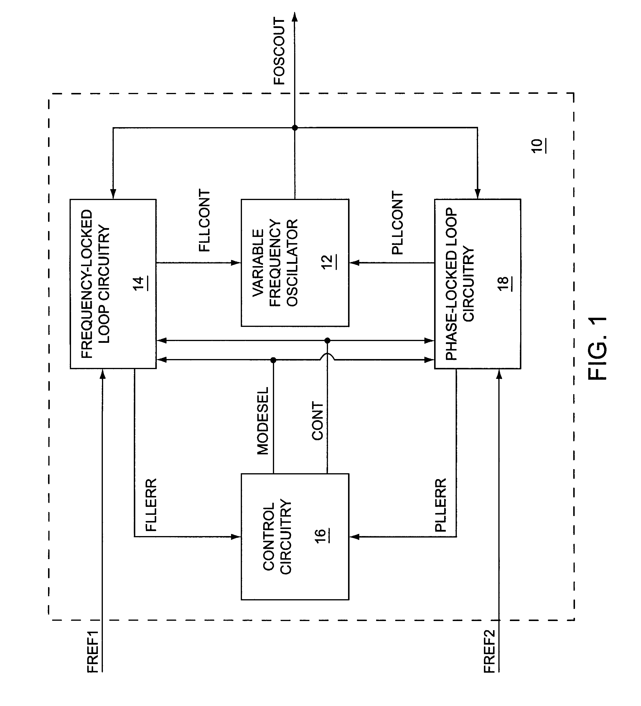
[0037]the present invention relates to a frequency and phase locked loop (FPLL) synthesizer having a frequency-locked loop (FLL) with an FLL operating mode and a phase-locked loop (PLL) with a PLL operating mode. The FLL operating mode is used for rapid coarse tuning of the FPLL synthesizer and is followed by the PLL operating mode for fine tuning and stabilization of the frequency of an output signal from the FPLL synthesizer. The FPLL synthesizer includes a variable frequency oscillator having a coarse tuning control input and a fine tuning control input. The coarse tuning control input is controlled by FLL circuitry, and the fine tuning input is controlled by PLL circuitry. The use of a frequency-locked loop allows faster settling time for the coarse tuning value than prior art linear and binary search methods. The FLL operating mode may be sub-divided into an FLL acquisition mode for rapid frequency tuning, and an FLL average and interpolate mode to complete frequency tuning bef...

fourth embodiment

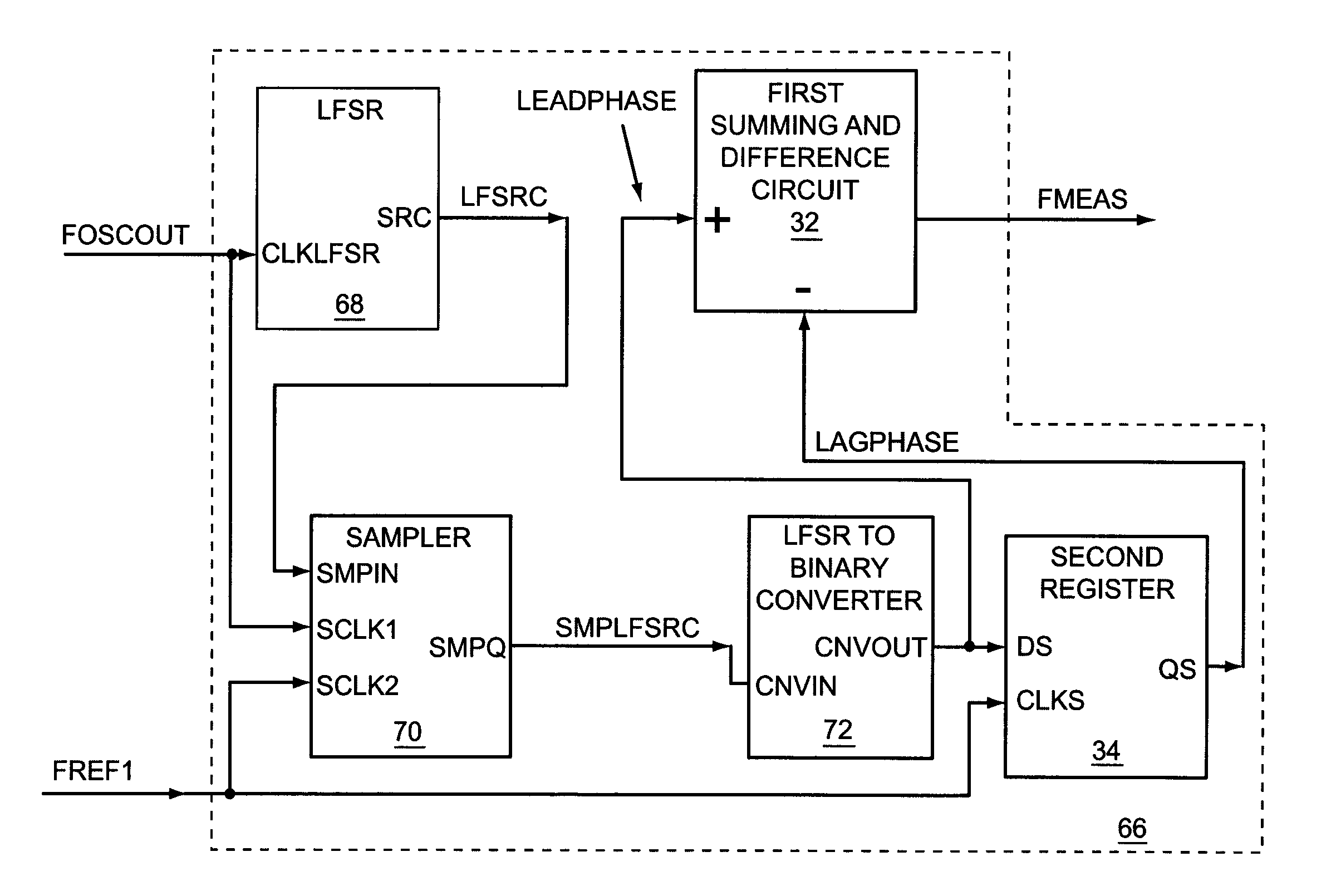
[0042]the present invention relates to combining the first and third embodiments of the present invention, which incorporates the high resolution frequency measurement circuit into the FLL circuitry of the FPLL circuitry, such that the high resolution frequency measurement circuit may directly receive the output of the variable frequency oscillator directly to provide high resolution, which may reduce settling times compared to FLL circuitry that uses frequency reduction.

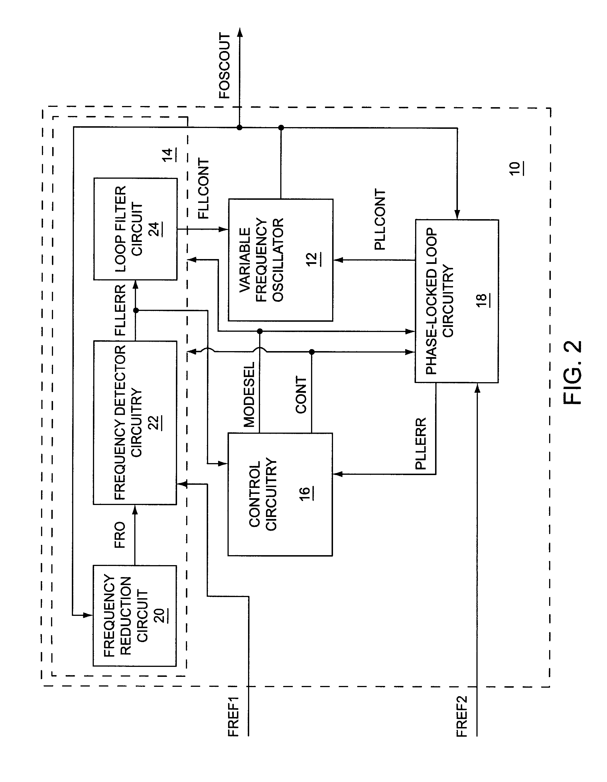
[0043]FIG. 1 shows an FPLL synthesizer 10, according to a first embodiment of the present invention. The FPLL synthesizer 10 includes a variable frequency oscillator 12, which provides a first oscillator output signal FOSCOUT. Frequency-locked loop circuitry 14 receives the first oscillator output signal FOSCOUT and a first frequency reference signal FREF1, and provides an FLL error signal FLLERR to control circuitry 16 and an FLL control signal FLLCONT to the variable frequency oscillator 12. The FLL control signal...


PUM


Abstract

A first embodiment of the present invention relates to a frequency and phase locked loop (FPLL) synthesizer having a frequency-locked loop (FLL) operating mode and a phase-locked loop (PLL) operating mode. The FLL operating mode is used for rapid coarse tuning of the FPLL synthesizer and is followed by the PLL operating mode for fine tuning and stabilization of the frequency of an output signal from the FPLL synthesizer. A second embodiment of the present invention relates to a high resolution frequency measurement circuit that is capable of directly measuring the frequency of a high frequency signal to provide a high resolution frequency measurement using a lower frequency reference signal, and may include linear feedback shift register (LFSR) circuitry and LFSR-to-binary conversion circuitry. A third embodiment of the present invention relates to an FPLL having an FLL that includes the high resolution frequency measurement circuit.

Description

[0001]This application is a Continuation-in-Part of U.S. utility application Ser. No. 11 / 854,917 entitled FREQUENCY AND PHASE LOCKED LOOP SYNTHESIZER, filed Sep. 13, 2007, currently pending, which claims the priority of provisional application 60 / 825,479 filed Sep. 13, 2006. U.S. utility application Ser. No. 11 / 854,917 is also a Continuation-in-Part of U.S. utility application Ser. No. 11 / 082,277 entitled DIGITAL FREQUENCY LOCKED LOOP AND PHASE LOCKED LOOP FREQUENCY SYNTHESIZER, filed Mar. 17, 2005, which issued as U.S. Pat. No. 7,279,988 on Oct. 9, 2007. The disclosures of all the above-identified applications are incorporated herein by reference in their entireties.FIELD OF THE INVENTION[0002]The present invention relates to frequency measurement circuits and frequency synthesizers in general and in particular to frequency-locked and phase-locked loop synthesizers, which may be used in radio frequency (RF) circuitry.BACKGROUND OF THE INVENTION[0003]Conventional frequency synthesiz...

Claims


Application Information

Patent Timeline
Patent Type & Authority Patents(United States)
IPC IPC(8): H03K9/06H03D3/00
CPCH03L7/087H03L7/099H03L7/10H03L7/18H03L2207/12H03L7/113
Inventor BUNCH, RYANJANESCH, STEPHEN T.
Owner QORVO US INC
Why Eureka
Try Eureka