Oil supply for an internal combustion engine

a technology for internal combustion engines and oil supply, which is applied in the direction of engine lubrication, engine cooling apparatus, mechanical apparatus, etc., can solve the problems that the piston bolt connection to the connecting rod is subject to particularly high load, and the bearing of the piston bolt cannot be easily realized as a permanent lubricating bearing. , to achieve the effect of reducing the oil requirement, improving the oil supply, and reducing the oil supply ratio ratio ratio ratio ratio ratio ratio ratio ratio ratio ratio ratio ratio ratio ratio ratio ratio ratio ratio ratio ratio ratio ratio ratio ratio ratio ratio ratio ratio ratio ratio ratio ratio ratio ratio ratio ratio ratio ratio ratio ratio ratio ratio ratio ratio ratio ratio ratio ratio ratio ratio ratio ratio ratio ratio ratio ratio ratio ratio ratio ratio ratio ratio ratio ratio ratio ratio ratio ratio ratio ratio ratio ratio ratio ratio ratio ratio ratio ratio ratio ratio ratio ratio ratio ratio ratio ratio ratio ratio ratio ratio ratio ratio ratio ratio ratio ratio ratio ratio ratio ratio ratio ratio ratio ratio ratio ratio ratio ratio ratio ratio ratio ratio ratio ratio ratio ratio ratio ratio ratio ratio ratio ratio ratio ratio ratio ratio ratio ratio ratio ratio ratio ratio ratio ratio ratio ratio ratio ratio ratio ratio ratio ratio ratio ratio ratio ratio ratio ratio ratio ratio ratio ratio ratio ratio ratio ratio ratio ratio ratio ratio ratio ratio ratio ratio ratio ratio ratio ratio ratio ratio ratio ratio ratio ratio ratio ratio ratio ratio ratio ratio ratio ratio ratio ratio ratio ratio ratio ratio ratio ratio ratio ratio ratio ratio ratio ratio ratio ratio ratio ratio ratio ratio ratio ratio ratio ratio ratio ratio ratio ratio ratio ratio ratio ratio ratio ratio ratio ratio ratio ratio ratio ratio ratio ratio ratio ratio ratio ratio ratio ratio ratio ratio ratio ratio ratio ratio ratio ratio ratio ratio ratio ratio ratio ratio ratio ratio ratio ratio ratio ratio ratio ratio ratio ratio ratio ratio ratio ratio ratio ratio ratio ratio ratio ratio ratio ratio ratio ratio ratio ratio ratio ratio ratio ratio ratio ratio ratio ratio ratio ratio ratio ratio ratio ratio ratio ratio ratio ratio ratio ratio ratio ratio ratio ratio ratio ratio ratio ratio ratio ratio ratio ratio ratio ratio ratio ratio ratio ratio ratio ratio ratio ratio ratio ratio ratio ratio ratio ratio ratio ratio ratio ratio ratio ratio ratio ratio ratio ratio ratio ratio ratio ratio ratio ratio ratio ratio ratio ratio ratio ratio ratio ratio ratio ratio ratio ratio ratio ratio ratio ratio ratio ratio ratio ratio ratio ratio ratio ratio ratio ratio ratio ratio ratio ratio ratio ratio ratio ratio ratio ratio ratio ratio ratio ratio ratio ratio ratio ratio ratio ratio ratio ratio ratio ratio ratio ratio ratio ratio ratio ratio ratio

Inactive Publication Date: 2010-07-13
WACKER NEUSON SE
View PDF26 Cites 11 Cited by
  • Summary
  • Abstract
  • Description
  • Claims
  • Application Information

AI Technical Summary

Benefits of technology

[0008]The present invention is based on the object of further improving the oil supply for an internal combustion engine in order on the one hand to ensure a reliable functioning of the internal combustion engine through sufficient lubrication, and on the other hand to minimize the oil requirement.

Problems solved by technology

It has turned out that a piston bolt that connects the piston to a connecting rod, as well as the bearings of this bolt in the piston and in the connecting rod, are subjected to particularly high loading during operation of the internal combustion engine.
While most of the bearings of the engine can be permanently lubricated, the bearing of the piston bolt cannot easily be realized as a permanently lubricated bearing due to its high thermal and mechanical loading.

Method used


Image

  • Oil supply for an internal combustion engine
  • Oil supply for an internal combustion engine

Examples


Embodiment Construction

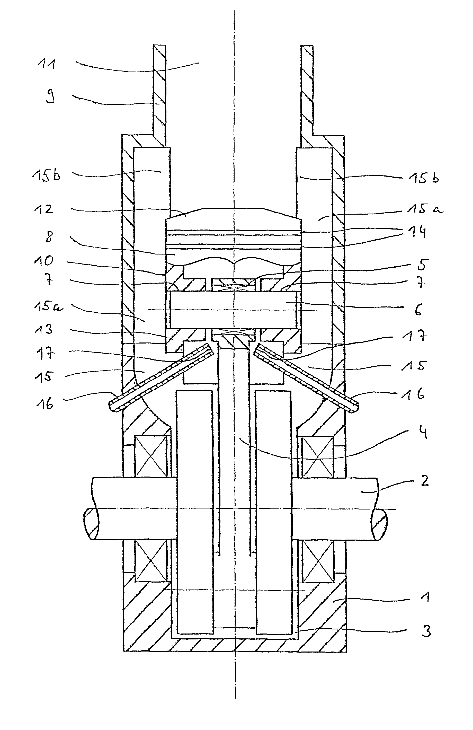
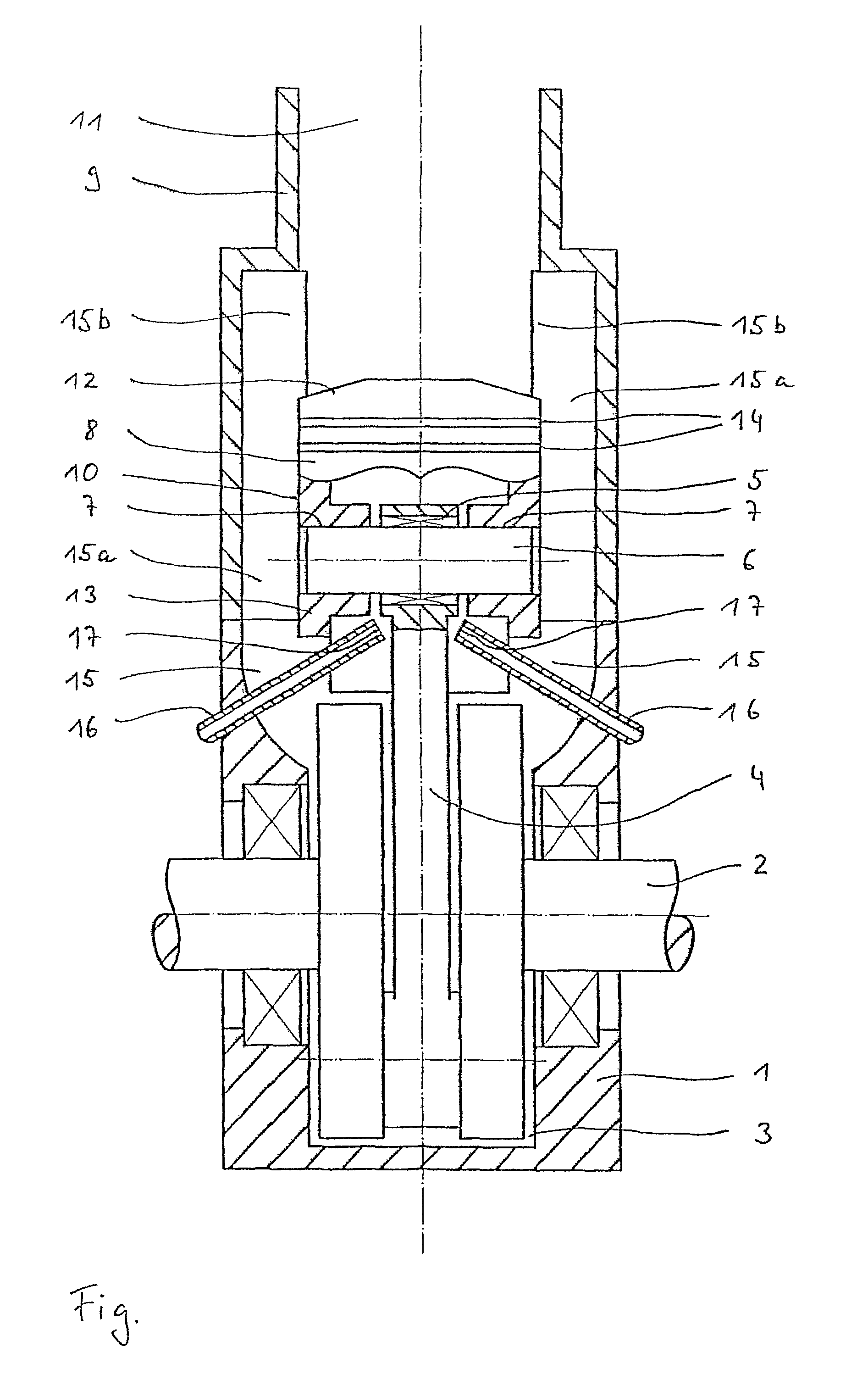
[0030]In an engine housing 1, a crankshaft 2 is mounted so as to be capable of rotation in a known manner. Crankshaft 2 passes through a crank chamber 3 provided in engine housing 1; a connecting rod 4, held on crankshaft 2 via a connecting rod bearing (not shown), also moves in this chamber in a known manner.

[0031]The end of connecting rod 4 situated opposite the connecting rod bearing supports, via an additional connecting rod bearing 5, a piston bolt 6. Piston bolt 6 passes on both sides through a respective piston bolt bore 7 formed in a piston 8. Piston 8 is capable of back-and-forth movement in a cylinder 9, and between piston 8 and cylinder 9 there exists a contact surface over which there is provided a piston contact surface 10 fashioned as a cylindrical jacket surface of piston 8.

[0032]Above piston 8, in cylinder 9 a combustion chamber 11 is present that is not shown in more detail in the FIGURE.

[0033]Piston 8 is essentially made of a piston base 12, which has a disk-shaped...


PUM


Abstract

The invention relates to an oil supply for an internal combustion engine, comprising an oil supply device for the supply of oil to a piston, reciprocating in a cylinder. The oil supply device is embodied such that at least at a point at which the piston is in the region of bottom dead centre, oil is introduced directly into a region below the piston, by means of the oil supply device, in particular, beneath the piston crown and within the piston skirt. The oil supply device thus comprises at least one tube element, extending into a region beneath the piston crown. The tube element terminates as close as possible to a gudgeon pin, when the piston is at bottom dead center. A targeted lubrication of the mechanically and thermally highly loaded gudgeon pin can thus be guaranteed. It is also possible by means of the oil supply to supply transfer ports of a two-stroke engine with oil, counteracting a tendency to coke up.

Description

BACKGROUND OF THE INVENTION[0001]1. Field of the Invention[0002]The present invention relates to an oil supply for an internal combustion engine as recited in the preamble of patent claim 1, as well as to an oil supply for a two-stroke engine as recited in the preamble of claim 12.[0003]2. Description of the Related Art[0004]Such an oil supply is known from DE 42 43 571 A1. According to this document, in an internal combustion engine a piston can execute back-and-forth movement in a cylinder, and oil can be sprayed against the piston via a nozzle. When the piston is situated in the area of its lower dead center, the oil is sprayed from the nozzle against the contact surface of the piston, and is distributed via grooves that run there on the periphery of the piston. When the piston is situated in the area of its upper dead center, the oil can be sprayed from the nozzle against the lower side of the piston, i.e. the piston base, in order to cool it. When there is a low load on the eng...

Claims


Application Information

Patent Timeline
Patent Type & Authority Patents(United States)
IPC IPC(8): F01M3/04F01M11/02F01M9/08F01M1/08F01M1/16F01P3/08
CPCF01M1/08F01P3/08F01M1/16F01M2001/086
Inventor HAUSLER, WOLFGANGSTENZEL, OTTO W.SICK, GEORG
Owner WACKER NEUSON SE
Why Eureka
Try Eureka