Device and method for active noise cancellation in exhaust gas channel of a combustion engine

a technology of active noise cancellation and combustion engine, which is applied in the direction of combustion air/fuel air treatment, instruments, nuclear elements, etc., can solve the problems of hardware reduction, and achieve the effect of simplifying the computation at run time, simple and efficient computation, and simple and efficient computation

Inactive Publication Date: 2010-07-13
ROBERT BOSCH GMBH
View PDF11 Cites 6 Cited by
  • Summary
  • Abstract
  • Description
  • Claims
  • Application Information

AI Technical Summary

Benefits of technology

[0007]Elimination of temperature sensors in the exhaust gas channel will result in reduced hardware. Reduction in hardware will directly result in savings in the cost. In addition, the absence of temperature sensors will eliminate: the requirements of wiring the temperature sensors to the electronic control unit using cables; periodic maintenance of the sensors in terms of calibrations; maintenance of the cables; replacements of hardware components when they are faulty, etc. If the calculated temperature is used to diagnose the signal of a given temperature sensor, then an easy method of diagnosis is made available which does not require a hardware element. Furthermore, the calculated temperature can be used in the case of a failure of the normal temperature sensor. In this manner, the overall system reliability is enhanced.
[0009]The major frequency component of the noise in the exhaust gas channel is estimated based on the engine speed. This involves a simple and efficient computation.
[0011]As the pre-stored data records are used to compute the dynamic part of the noise compensation, the control logic may be configured in a simple and efficient manner.
[0012]The relationship between the feedback signal and the temperature in the exhaust gas is available as pre-stored data, thereby simplifying the computations at run time.

Problems solved by technology

Elimination of temperature sensors in the exhaust gas channel will result in reduced hardware.

Method used


Image

  • Device and method for active noise cancellation in exhaust gas channel of a combustion engine
  • Device and method for active noise cancellation in exhaust gas channel of a combustion engine
  • Device and method for active noise cancellation in exhaust gas channel of a combustion engine

Examples


Embodiment Construction

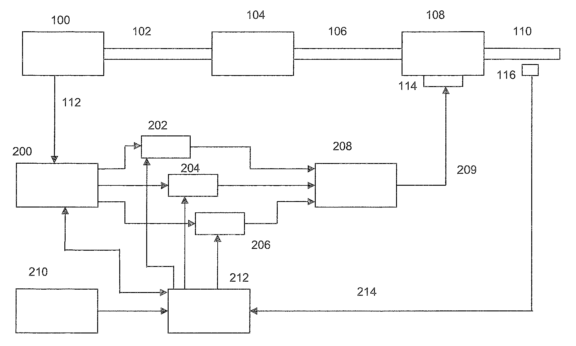
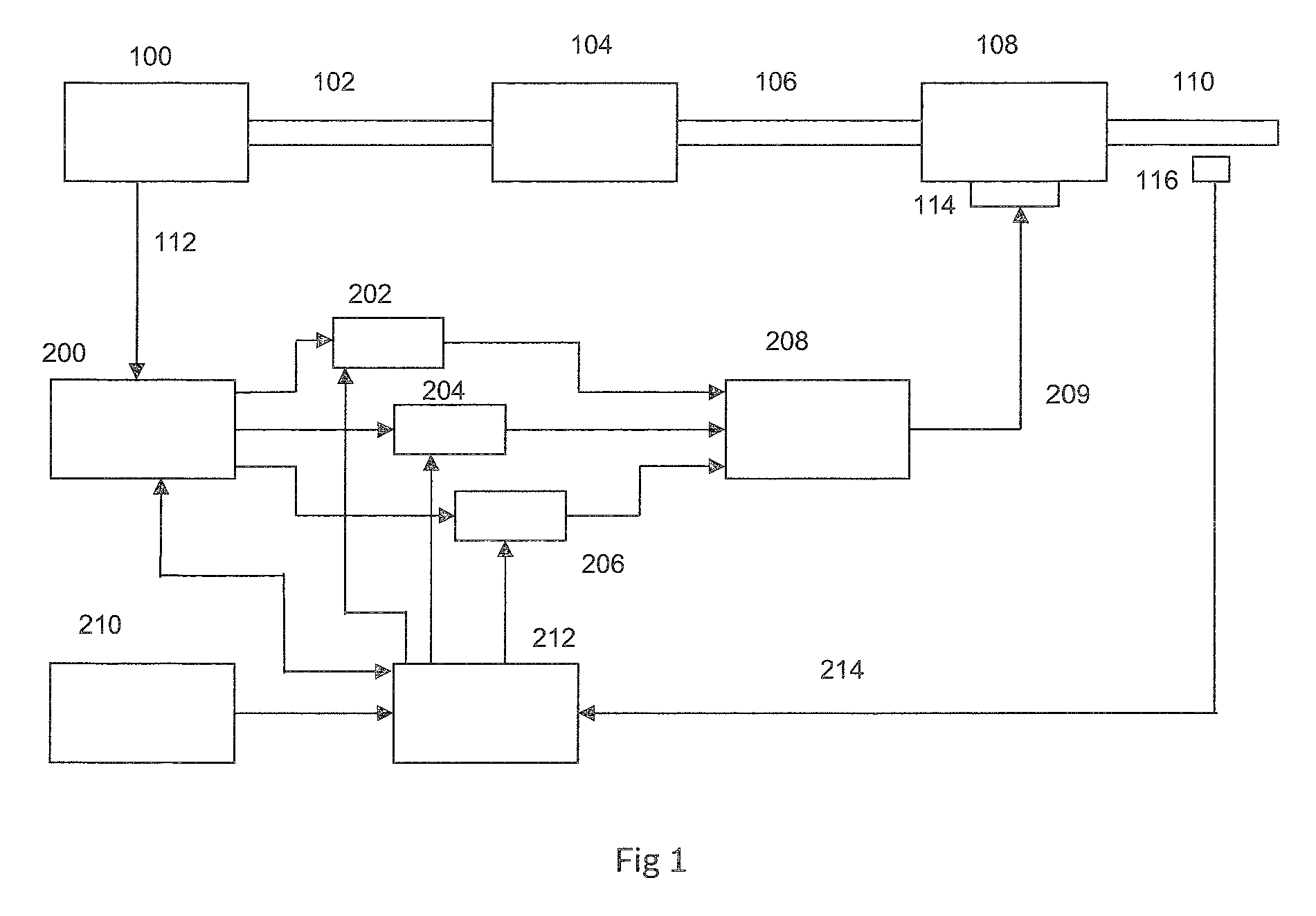
[0016]FIG. 1 shows a combustion engine 100 which is connected to an exhaust gas channel 102, 106 and 110. The exhaust gas channel includes an central muffler 104 and rear muffler 108. The combustion engine is connected over line 112 to the signal generator 200. The output of signal generator is connected to three digital filters 202, 204 and 206. The digital filters also receive inputs from the calculation means 212. The calculation means 212 refers to the data records 210 in order to control the filters. The outputs of the digital filters are given to an amplifier 208. The amplifier output is given to the sound converter 114 which is in close contact with the exhaust gas channel. The exhaust gas channel has a sound sensor 116 placed in it, and output of sound sensor is connected to calculation means 212.

[0017]The combustion engine 100 mixes fuel and air in a cylinder, which is ignited, resulting in kinetic energy to move the vehicle. The residual from the combustion engine passes t...


PUM

PropertyMeasurementUnit
frequencyaaaaaaaaaa
temperatureaaaaaaaaaa
speedaaaaaaaaaa

Abstract

In a method and a device for canceling the noise in an exhaust gas channel of a vehicle, a noise signal is received from the exhaust gas channel using a sound sensor, and a frequency signal which has the same amplitude and the opposite phase as the noise signal is generated. The generated frequency signal is acoustically mixed with the noise signal in the exhaust gas channel using a sound converter, there by reducing the noise in the exhaust gas channel. In addition, the temperature in the exhaust gas channel is calculated based on the received sound signal.

Description

BACKGROUND OF THE INVENTION[0001]1. Field of the Invention[0002]The present invention relates to a device and a method for active noise cancellation in exhaust gas channel of a combustion engine.[0003]2. Description of Related Art[0004]The published European patent document EP 0 840 285 already discusses a device for noise cancellation, with means to receive a sound signal from the exhaust gas channel, means to generate an anti noise signal, which, when acoustically coupled to the sound from exhaust gas channel, the result will be cancellation of both signals, resulting in reduction in noise.BRIEF SUMMARY OF THE INVENTION[0005]The present invention provides the following advantages:[0006]The present invention, which provides noise reduction in the exhaust gas channel of a combustion engine, additionally provides the ability to compute the temperature in the exhaust gas channel without a temperature sensor, and / or the ability to diagnose the present exhaust gas temperature sensors (i...

Claims


Application Information

Patent Timeline
Patent Type & Authority Patents(United States)
IPC IPC(8): F01N1/06F02M35/10G01L23/22G06F11/30G10K11/16
CPCG01R33/34007G01R33/341G01R33/5659G01R33/3873G01R33/3415
Inventor KASSNER, UWE
Owner ROBERT BOSCH GMBH
Why Eureka
Try Eureka