
Electric power control device, electric powered vehicle including the same, and method for controlling electric power of electric vehicle

a technology of electric power control and electric vehicle, which is applied in the direction of dynamo-electric converter control, multiple dynamo-motor starters, transportation and packaging, etc., can solve the problems of reducing the size, weight, cost and the like of a vehicle, and achieves weight reduction, size reduction, cost reduction

Inactive Publication Date: 2010-07-13
TOYOTA JIDOSHA KK
View PDF24 Cites 7 Cited by
  • Summary
  • Abstract
  • Description
  • Claims
  • Application Information

AI Technical Summary

Benefits of technology

The present invention provides an electric power control device and an electric powered vehicle that can supply electric power to a vehicle-mounted load without using a dedicated voltage conversion device such as a DC / DC converter. The device includes a first polyphase AC motor, a second polyphase AC motor, a first power storage device, a second power storage device, and a voltage control portion that controls the voltage across the first and second neutral points in accordance with the request voltage for the vehicle-mounted load. The vehicle-mounted load can include a DC load, and the voltage control portion generates a DC voltage across the first and second neutral points in accordance with the request voltage for the DC load. The electric power control device allows for stable supply of electric power to the vehicle-mounted load without the need for a DC / DC converter. The electric powered vehicle includes the electric power control device and a driving wheel that is mechanically linked to a rotation shaft of at least one of the first and second polyphase AC motors, and the vehicle-mounted load is electrically connected between the first and second neutral points of the first polyphase AC motor and the second polyphase AC motor. This eliminates the need for a dedicated voltage conversion device and reduces size, weight, and cost of the vehicle.

Problems solved by technology

However, the electric power control device still requires the DC / DC converter for converting the high voltage from the main battery to the low voltage.
However, provision of a DC / DC converter for each power supply system hinders size reduction, weight reduction, cost reduction and the like of a vehicle.

Method used


Image

  • Electric power control device, electric powered vehicle including the same, and method for controlling electric power of electric vehicle
  • Electric power control device, electric powered vehicle including the same, and method for controlling electric power of electric vehicle
  • Electric power control device, electric powered vehicle including the same, and method for controlling electric power of electric vehicle

Examples


embodiment 1

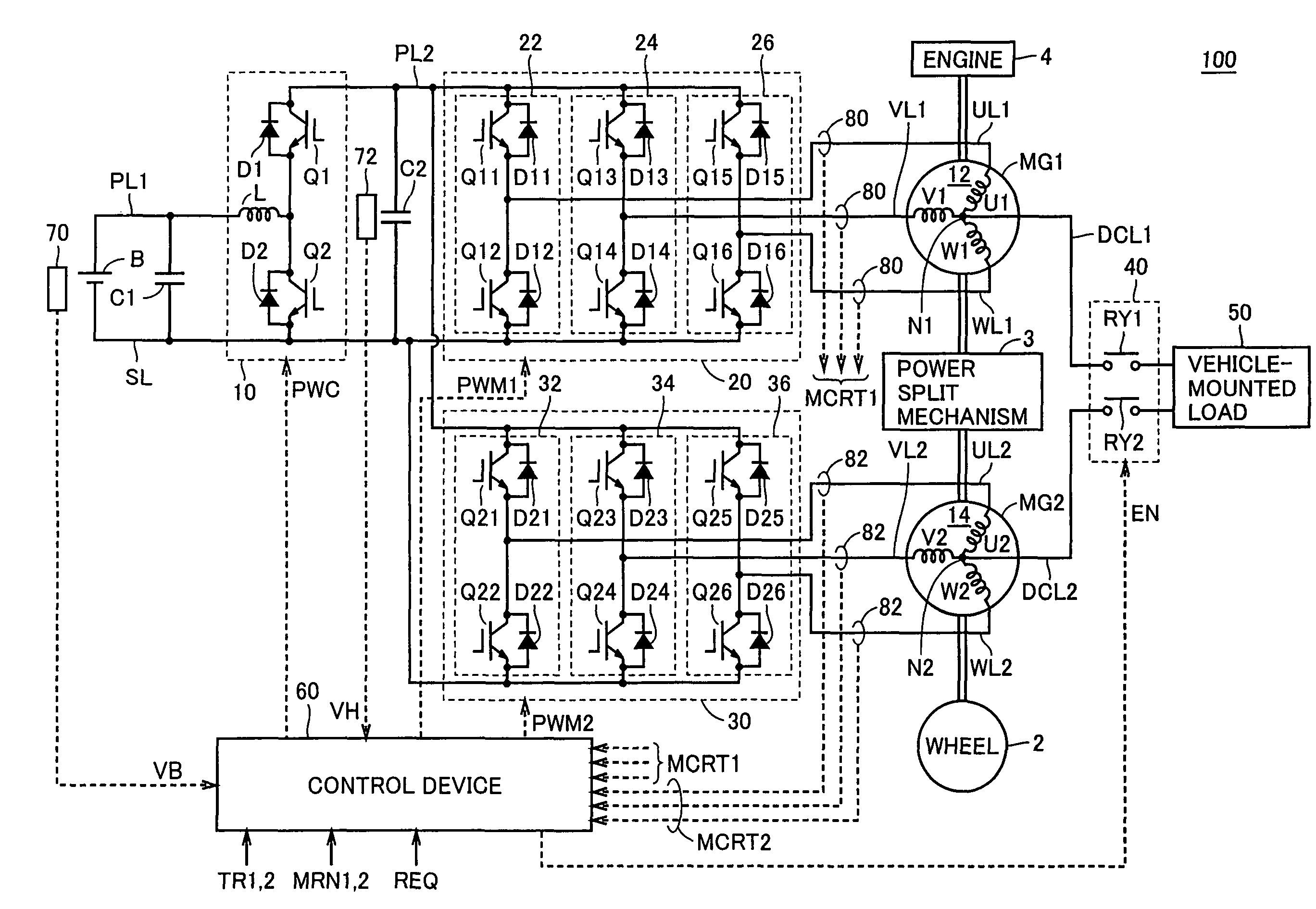
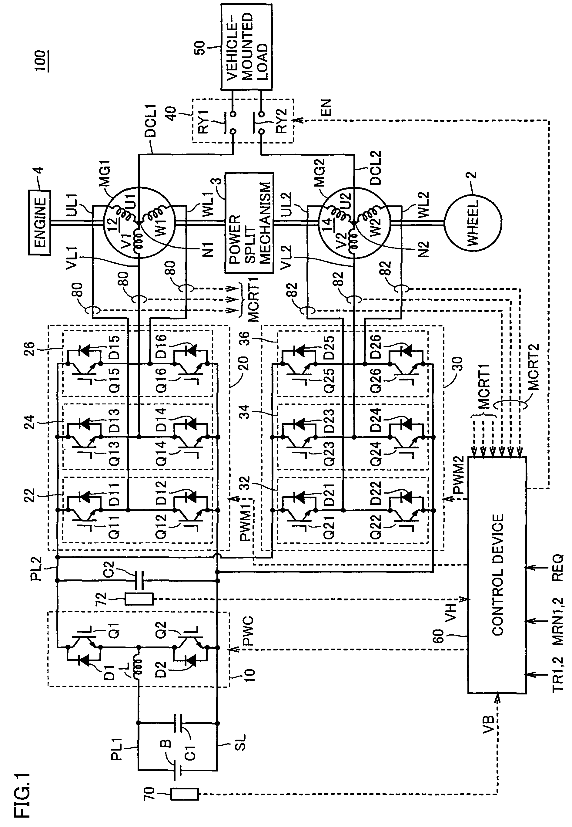
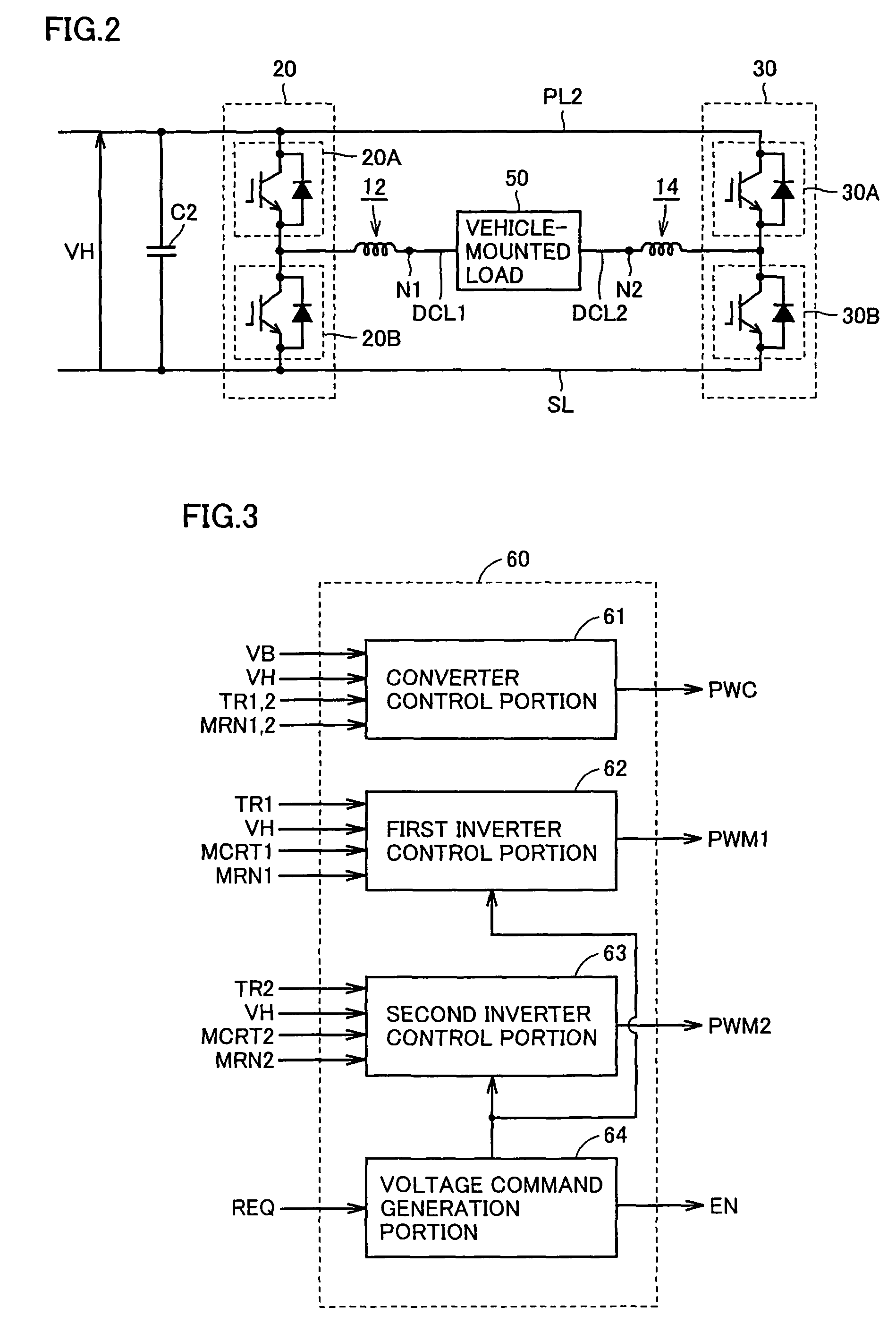
[0030]FIG. 1 is a general block diagram of a hybrid vehicle 100 shown as one example of an electric powered vehicle according to Embodiment 1 of the present invention. With reference to FIG. 1, hybrid vehicle 100 includes an engine 4, motor generators MG1 and MG2, a power split mechanism 3, and wheels 2. Hybrid vehicle 100 also includes a power storage device B, a boost converter 10, inverters 20 and 30, a control device 60, capacitors C1 and C2, power supply lines PL1 and PL2, a grounding line SL, U-phase lines UL1 and UL2, V-phase lines VL1 and VL2, W-phase lines WL1 and WL2, voltage sensors 70 and 72, and current sensors 80 and 82. Hybrid vehicle 100 also includes power output lines DCL1 and DCL2, a relay circuit 40, and a vehicle-mounted load 50.

[0031]Hybrid vehicle 100 runs with engine 4 and motor generator MG2 being used as a motive power source. Power split mechanism 3 distributes motive power to engine 4, motor generator MG1 and motor generator MG2 each linked thereto. For e...

embodiment 2

[0083]FIG. 6 is a general block diagram of a hybrid vehicle 100A shown as one example of an electric powered vehicle according to Embodiment 2 of the present invention. With reference to FIG. 2, hybrid vehicle 100A is different in configuration from hybrid vehicle 100 according to Embodiment 1 shown in FIG. 1. Specifically, hybrid vehicle 100A includes a switch circuit 92, auxiliary batteries B1 and B2, load groups 94 and 96, power supply lines PL3 and PL4, and grounding lines SL3 and SL4, in place of relay circuit 40 and vehicle-mounted load 50. Hybrid vehicle 100A also includes a control device 60A in place of control device 60.

[0084]Switch circuit 50 has a pair of input terminals connected to power output lines DCL1 and DCL2, respectively, a first pair of output terminals connected to power supply line PL3 and grounding line SL3, respectively, and a second pair of output terminals connected to power supply line PL4 and grounding line SL4, respectively.

[0085]Auxiliary battery B1 h...


PUM


Abstract

A load on a vehicle is connected to first and second neutral points in first and second motor generators through a relay circuit and power output lines. A control device controls inverters depending on a requested voltage of the load on a vehicle such that a potential at the first neutral point becomes higher than a potential at the second neutral point by that requested voltage.

Description

TECHNICAL FIELD[0001]The present invention relates to an electric power control device, and an electric powered vehicle including the same. In particular, the present invention relates to an electric power control device that steps down a voltage from a power storage device for main machinery and supplies a resultant voltage to a vehicle-mounted load, and an electric powered vehicle including the same.BACKGROUND ART[0002]An electric powered vehicle such as an electric vehicle or a hybrid vehicle requires a high-voltage source for main machinery and a low-voltage source for auxiliaries. Conventionally, a DC / DC converter reduces a direct current (DC) voltage outputted from the high-voltage source for the main machinery to obtain a low voltage for the auxiliary.[0003]Japanese Patent Laying-Open No. 7-170611 discloses an electric power control device for an electric vehicle, including such a DC / DC converter. The electric power control device includes a main battery, and a DC / DC converte...

Claims


Application Information

Patent Timeline
Patent Type & Authority Patents(United States)
IPC IPC(8): H02P1/54B60L9/18B60R16/033
CPCH02M7/487H02M7/493H02P27/08H02P5/74
Inventor OYOBE, HICHIROSAISASAKI, SHOICHINAKAMURA, MAKOTOISHIKAWA, TETSUHIRO
Owner TOYOTA JIDOSHA KK
Learn More