RFID tag and method of manufacturing the same

a radio frequency identification and tag technology, applied in the field of wireless communication devices, can solve the problems of high undesirable, high cost of molds, and tags that are not well suited for use on metallic items, and achieve the effect of high throughput ra

Active Publication Date: 2010-07-13
CASCADE ENG
View PDF70 Cites 23 Cited by
  • Summary
  • Abstract
  • Description
  • Claims
  • Application Information

AI Technical Summary

Benefits of technology

[0014]It is yet another object of the present invention to provide an RFID tag and method of manufacturing the same that is well-suited for mass-production at a high rate of throughput.

Problems solved by technology

Although RFID tags of the type described above are suitable for use on many different types of items, such tags are not well-suited for use on metallic items for the reason that metallic items tend to interfere with the RF signal transmitted by the RFID tag antenna.
This is highly undesirable as molds are quite expensive.
As noted above, each tag is manufactured, one at a time, using a labor-intensive and time-consuming process.

Method used


Image

  • RFID tag and method of manufacturing the same
  • RFID tag and method of manufacturing the same
  • RFID tag and method of manufacturing the same

Examples


first embodiment

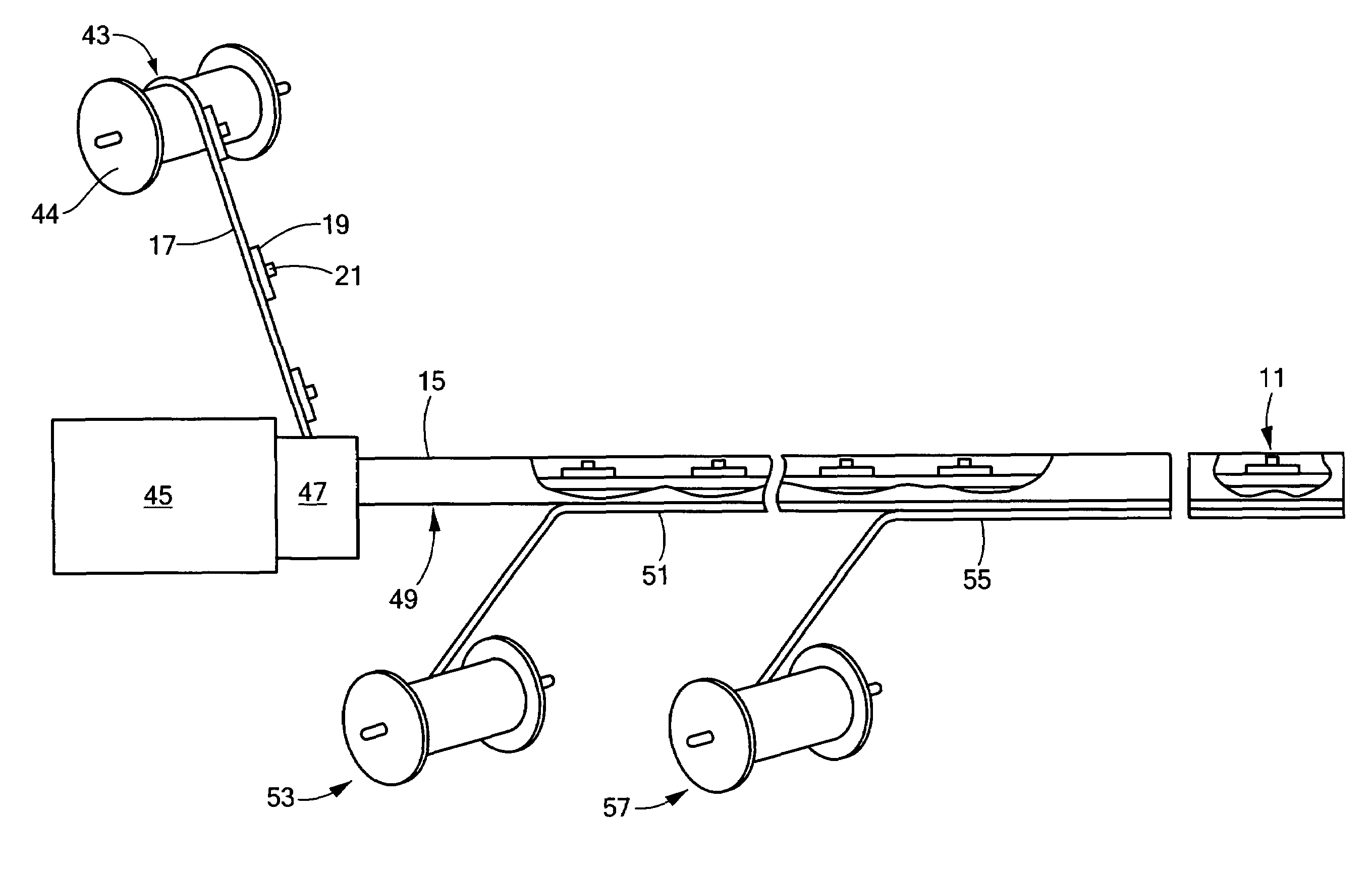
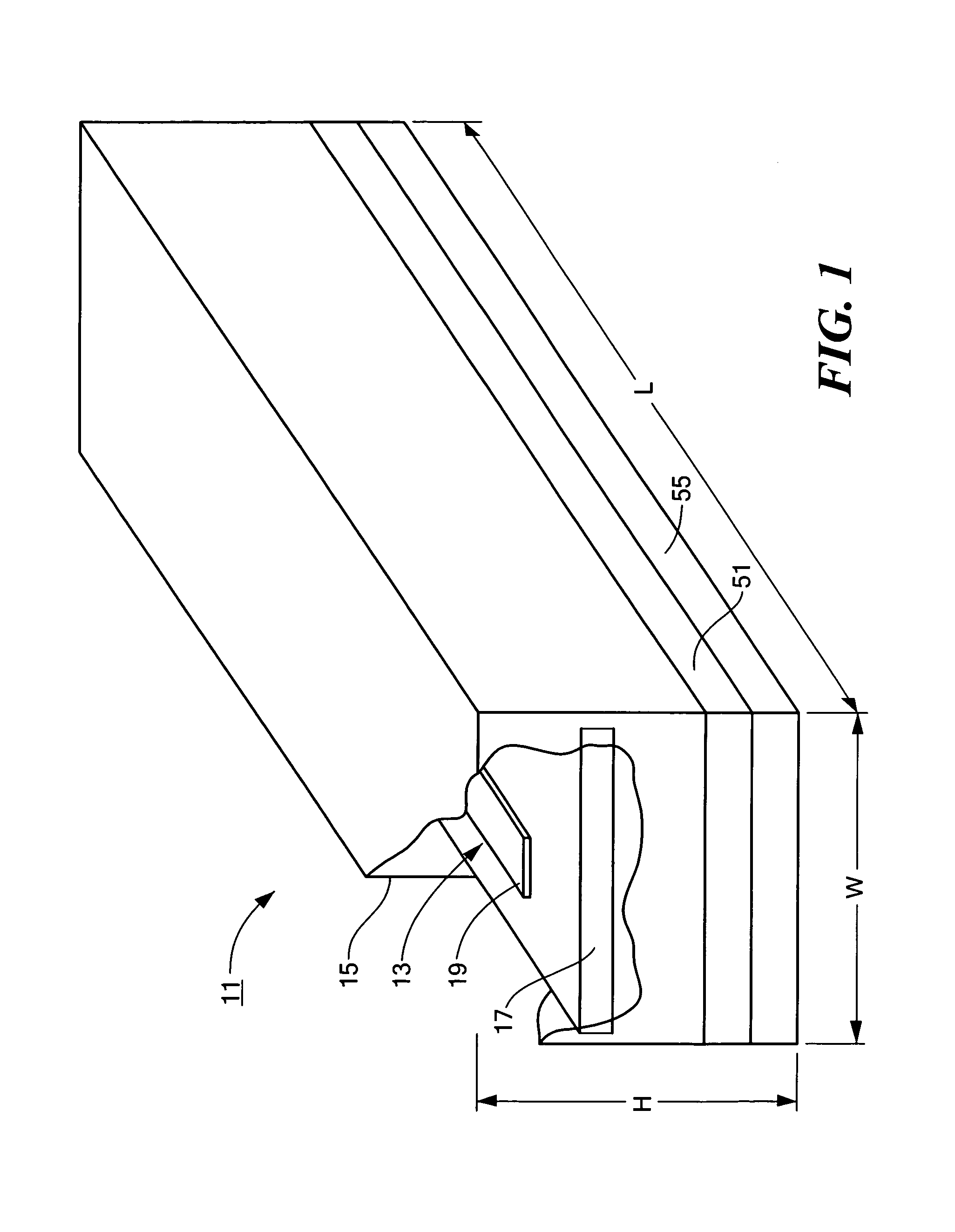
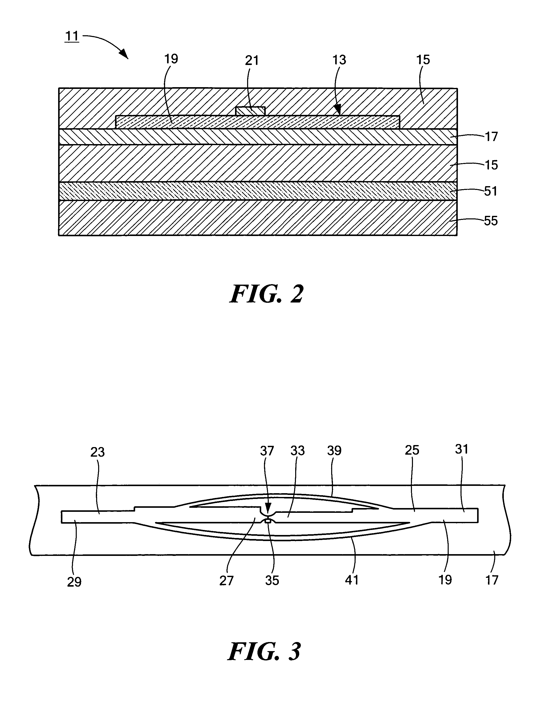
[0038]Referring now to FIGS. 1 and 2, there are shown perspective and section views, respectively, of a radio frequency identification (RFID) tag constructed according to the teachings of the present invention and identified generally by reference numeral 11. In operation, RFID tag 11 is designed to be affixed onto a particular item (or packaging therefor) and, in response to an active or passive radio frequency signal, wirelessly transmit information relating to said item.

[0039]RFID tag 11 comprises a radio frequency (RF) inlay 13 and a plastic extrudate 15, extrudate 15 surrounding or enveloping inlay 13 in the manner to be described below.

[0040]RF inlay 13 includes a carrier sheet 17, an antenna 19 formed on carrier sheet 17 and a wireless communication device 21 mounted on antenna 19.

[0041]Carrier sheet 17 preferably comprises a heat-stable polymeric film having a thickness in the range of about 2 mm to 5 mm. Examples of materials suitable for use as carrier sheet 17 include, bu...

second embodiment

[0061]As an example, referring now to FIGS. 5 and 6, there are shown perspective and section views, respectively, of a radio frequency identification (RFID) tag constructed according to the teachings of the present invention and identified generally by reference numeral 111.

[0062]RFID tag 111 is similar to RFID tag 11 in that RFID tag 111 includes a radio frequency (RF) inlay 113 which is identical to RF inlay 13. Specifically, RF inlay 113 comprises an elongated carrier sheet 117 preferably manufactured as a continuous web of heat-stable polymeric film, an antenna 119 printed directly onto the top surface of carrier sheet 117 and a wireless communication device 121 conductively bonded to antenna 119.

[0063]However, RFID tag 111 differs from RFID tag 11 in that RF inlay 113 is positioned within a two-piece plastic casing 115 whereas RF inlay 13 is positioned within a unitary plastic extrudate 15.

[0064]Specifically, casing 115 includes an elongated bottom member 123 which is manufactu...

third embodiment

[0074]Referring now to FIGS. 8 and 9, there are shown perspective and section views, respectively, of a radio frequency identification (RFID) tag constructed according to the teachings of the present invention and identified generally by reference numeral 171.

[0075]Tag 171 is similar in most respects to tag 111, the principal difference between the two tags being that tag 171 does not include a top member 127. Instead, tag 171 includes a plug 177, plug 177 being positioned directly on top of inlay 113 and occupying some or all of the remaining space of cavity 125 of bottom member 123. Accordingly, as can readily be appreciated, tag 171 does not possess an air gap over inlay 113 of the type described above in connection with tag 111.

[0076]Plug 177 may be formed, for example, by extruding molten plastic over inlay 113 until cavity 125 is partially or completely filled and then allowing the molten plastic to cool and harden in place. Alternatively, plug 177 may be formed by pouring int...


PUM


Abstract

A radio frequency identification (RFID) tag and method of manufacturing the same. In a preferred embodiment, the RFID tag includes a radio frequency (RF) inlay, the RF inlay including a carrier sheet, an antenna printed on the carrier sheet and a wireless communication device bonded to the antenna. The RFID tag also includes a plastic extrudate, the RF inlay being disposed within the extrudate so that the antenna and the wireless communication device are encapsulated on all sides within the extrudate. Optional metallic reflector and mounting adhesive layers may be laminated onto the underside of the extrudate. The present invention is also directed to an automated method for manufacturing the above RFID tag, such a method involving, in one embodiment, feeding a continuous supply of RF inlays into a cross-head extruder to yield a continuously extruded block and then cutting the block between successive antennae to yield a plurality of individual RFID tags.

Description

BACKGROUND OF THE INVENTION[0001]The present invention relates generally to wireless communication devices and more particularly to a novel radio frequency identification (RFID) tag and to a method of manufacturing said RFID tag.[0002]Current inventory and manufacturing methods rely on the ability to track and identify items, such as packages, containers, individual parts, inventory items or other similar items of concern, and to communicate information relating to said items in a wireless manner. One method of tracking and providing information relating to an item is to incorporate a wireless communication device, such as an active or passive transponder, into an identification tag that responds to wireless interrogation and commands and, in turn, to attach said identification tag directly to the item. The tag is preferably designed to store or represent pertinent information relating to the item to which it is attached, such as a unique identifying number, an expiration date, a “b...

Claims


Application Information

Patent Timeline
Patent Type & Authority Patents(United States)
IPC IPC(8): G08B13/14G06K19/077
CPCG06K19/07718G06K19/07745G06K19/07749G06K19/07771H01L2924/0002H01L2924/00
Inventor CULLEN, JAMES M.HERRMANN, CHARLES K.PULESTON, DAVID J.
Owner CASCADE ENG
Why Eureka
Try Eureka